Hi all
I have decided to build Frank´s pre-amplifier and Bruce Rozenblitz (Glass Audio) 6AS7 OTL power amplifier http://www.bonavolta.ch/hobby/fr/audio/6as7_2.htm. I´m living in Brazil right now, where it is pretty hard to get tubes, so I brought all of them from the Netherlands.
I thought a lot about how to build the amplifiers, especially about possible upgrades in the future and flexibility of connection (I´m only 21 years old).
Right now I don’t need to work with crossovers or lots of power, because I am using Fostex 208 Sigma as speaker. Probably I will use two 15” subwoofers for the low frequencies, and I am planning to drive those with an active filtered gainclone or a Harman Kardon PM655. Has anyone got a good recommendation not to do this? Returning to tubes.
About the pre-amplifier. This is an unbalanced design, which is good enough for me right now. I have been thinking about designing the amplifier chassis and the power supply in such a way that it can be turned in a balanced pre amplifier. I still have to look for material about such an implementation, but I think adding one more 12BH7A in the same way and driving both from a balanced signal is everything I have to do. (For unbalanced signals I can use a trafo or IC as phase splitter before the 12BH7A.) Am I right assuming this? If not, please correct me and suggest me how much space I have to leave on the chassis to turn it into a balanced design.
To Frank, who developed this pre amplifier: If I am right when assuming that adding one more 12BH7A is sufficient to turn this design into a balanced one: is it possible to drive both valves with the same power supply using the 250V/300mA trafo? Or can I better get a trafo with some more VA? (
I am planning to implement a volume control like the one used in Aleph 1. Till (and Future) have developed something similar at http://home.arcor.de/dddddd-/index.html. I thought about using the next values of resistors: 5k(MSB), 10k, 20k, 40k, 80k, 160k, 320k, 640k(LSB). The lowest input impedance of this volume control will be around 10k, the highest something near 640k. If I am wrong assuming the input impedance will change, correct me. Right now I am using a Meridian 206 as source. I think neither the 10k or the 260k will hurt the CD player. A question to Frank again: Will the preamplifier work well with such a varying impedance curve? I realize that besides changing input impedance the output impedance of this control will change too.
The power amplifier, another well known from Frank. My first plans where to build three chassis. One with the power supply with the same ratings as Mr. Rozenblitz suggest and two chassis, each for one amplifier. I would already leave space for 8 6AS7 on each chassis, but use only 4 for the moment (I don´t need more power right now and I don´t have the money for all the trafo´s). Whenever I need more power I could fit 4 more 6AS7 in each chassis, build another power supply and use one power supply at each channel. Some things have changed my thought, though. First: I think I could have a great possibility of a ground loop. (Umbilical’s with ground connection would be going to each amplifier, and the amplifiers are already connected to each other with the ground of the pre-amplifier.) I realized that adding one more tube (a 6SN7) to each chassis would give me much greater flexibility in the use of the amplifier in the future. I would have 2 channels with 4 6AS7 on each in one chassis. At the first moment I can use it as a stereo amplifier. Whenever I build a second amplifier, with the same configuration, I will have 4 channels, which I can use for biamplification, bridging both channels (already thinking at the balanced chain: DAC, still to build, balanced preamplifier and balanced power amplifier. I realize I would have to use at least an 8 ohm speaker) or I could make a single channel with 8 6AS7 per channel, getting more power.
I would like to hear your comments, critics, suggestions, ideas, opinions etc. Thanks in advance.
Erik
I know that this response may be obvious, but by all means, make your enclosures large enough to accomodate any future revisions that you may have in mind. There's nothing worse than realizing that you're going to have to dismantle your entire amp just to make one update.
Sorry that I can't answer the "Frank" questions, but I doubt that you could go wrong with the two.
P.S.
I've never met Frank. Frank has never been a friend of mine. But I'm no Frank(lame American political humor).
Sorry that I can't answer the "Frank" questions, but I doubt that you could go wrong with the two.
P.S.
I've never met Frank. Frank has never been a friend of mine. But I'm no Frank(lame American political humor).
Hi,
Erik, there were plenty of tubes in the Santa Ifiginia barrio in Rio de Janeiro 10 years ago...6AS7s made by RCA, whatever, at low cruzado prices...Same thing in Sao Paolo.
Regarding the Rosenblit OTL, it would easiest for you to build two monoblocks iso two plus a separate PSU.
Just use the same specs for the xformer as per BR on a per channel basis, use the 12AX7A as a diff amp and put the 6SN7 in // to drive 8 tubes iso 4.
For the regulator I used two OB2s, stacked, to replace the noisy zeners...that's it for the amp.
Even though you may have highly efficient speakers, I'd still recommend using 8 output tubes for better bass performance.
Now for the pre, I assume you're talking about the linestage WCF part?
If you want to turn that into a balanced stage, just build everything double from start to finish. That's both the easiest and best way you can have both balanced and unbalanced operation from such a stage.
When run unbalanced just short the output/input of the inverting stage.
For the volctrl, I'd recommend a constant impedance 1 Meg balanced attenuator control, one per channel.
I insist on the 1M since it works best with this topology.
Try to keep connecting wire/cable capacity as low as possible.
Also keep in mind that this preamp presents a small insertion loss and it is nothing more than a passive preamp with a hefty current capacity.
Cheers,
Hi,
Sorry...I forgot something:
It may be worthwhile to try crosscoupling the drivers to the output stage of the OTL.
I haven't tried it myself but I think it should work.
Don't forget to swap the bias accordingly...
Also, I used a FWBR for the bias of the tubes using Schottky diodes.
Cheers,
Sorry...I forgot something:
It may be worthwhile to try crosscoupling the drivers to the output stage of the OTL.
I haven't tried it myself but I think it should work.
Don't forget to swap the bias accordingly...
Also, I used a FWBR for the bias of the tubes using Schottky diodes.
Cheers,
Thanks for the replies
Frank
I don´t know how to parallel the 6SN7 or use the ECC83 as diferential amplifier, but I am going to find it out (I hope). I will check at the shops in São Paulo and Rio about the disponible tubes. Maybe they have the OB2, so I can take the zeners out of the circuit.
Next weekend the chassis for the pre-amplifier will be ready and during the week I hope to conclude a 807SE, schematics posted through Frank too. Listining to this set, I will think further about the 6AS7.
Hi,
Hum...I've been a little hasty regarding the differential stage at the input.
I had forgotten about the intermediate and driverstages.
What you'd need is balun stage at the input using the 2 triodes of the 12AX7 and retain the gain of that stage....
Than, there's the NFB loop to consider as well...
Now, assuming you haven't lost interest altogether putting the last 6SN7GT in // is actually very easy to do:
You need 2 more 33K 1W resistors and proceed as follows:
Connect a 33K resistor to pin # 5 and # 6 of the tube ( always look at the pins/socket from the bottom and go clockwise).
Wire each resistor's remaing leadout wire to corresponding other one, namely R10 and R11.This is were the voltages are shared between the two halves.
Now connect grid pins #s 1 and 4 together and that's all there is to it.
If in doubt please do ask.
In case you intend to use 8 output tubes I'd recommend using at least 2 4700µF/200V caps on each pole of the bipolar rail (+/- 150VDC)
All tubes were fed from AC with no hum whatsoever.
Hope this helps.
Cheers,
I don´t know how to parallel the 6SN7 or use the ECC83 as diferential amplifier, but I am going to find it out (I hope).
Hum...I've been a little hasty regarding the differential stage at the input.
I had forgotten about the intermediate and driverstages.
What you'd need is balun stage at the input using the 2 triodes of the 12AX7 and retain the gain of that stage....
Than, there's the NFB loop to consider as well...
Now, assuming you haven't lost interest altogether putting the last 6SN7GT in // is actually very easy to do:
You need 2 more 33K 1W resistors and proceed as follows:
Connect a 33K resistor to pin # 5 and # 6 of the tube ( always look at the pins/socket from the bottom and go clockwise).
Wire each resistor's remaing leadout wire to corresponding other one, namely R10 and R11.This is were the voltages are shared between the two halves.
Now connect grid pins #s 1 and 4 together and that's all there is to it.
If in doubt please do ask.
In case you intend to use 8 output tubes I'd recommend using at least 2 4700µF/200V caps on each pole of the bipolar rail (+/- 150VDC)
All tubes were fed from AC with no hum whatsoever.
Hope this helps.
Cheers,
Questions about DS and paralleling
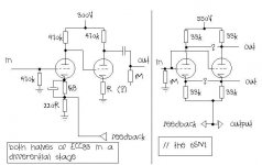
After some search on the net I have found three links related to a differential stage. I drew what I think must be the ECC83 in a differential stage. I don´t think it is right (it seems to simple to be right). If it is right, I don´t know the value of R in the schematic. I believe R determines the gain of the stage, and I´m looking for a gain of 1.
I also drew the // 6SN7. I´m not sure about the lines connecting both pins # 2 and # 5 to the output; # 3 and # 6 to the inverted output.
I am curious why they use a 2,2muF/630V coupling cap. This is a rather great and hard to find value. In most schematics I see 0,1 or something close being used. I used the crossover formula and got 0,07Hz crossover frequency (for 2,2muF and 1M resistor). What happens if I use a smaller cap there?
I already ordered the trafo´s (EI). I will spent less than 40 euros per channel (8 output tubes) in trafo´s. I think they are of good quality, because the factory gives one year warranty.
Attachments
Hi Erik,
If it were me I'd drop the idea of the differential input stage.
That drawing is correct.
That formula doesn't apply here as the 1M resistor isn't referenced to ground.
Cheers,
If it were me I'd drop the idea of the differential input stage.
I´m not sure about the lines connecting both pins # 2 and # 5 to the output; # 3 and # 6 to the inverted output.
That drawing is correct.
I used the crossover formula and got 0,07Hz crossover frequency (for 2,2muF and 1M resistor). What happens if I use a smaller cap there?
That formula doesn't apply here as the 1M resistor isn't referenced to ground.
Cheers,
Thanks Frank
Thanks for your reply.
I will do some more search on the differential stage at the ECC83, but will start building the amplifier without it. Just tell me one more thing...how "large" (how much volume) will the differential stage take? (I don´t think much) I am asking it because I can already plan some free space for future implementation.
Erik
Hi,
The space needed for the noval socket alone should be enough.
Cheers,
Just tell me one more thing...how "large" (how much volume) will the differential stage take? (I don´t think much) I am asking it because I can already plan some free space for future implementation.
The space needed for the noval socket alone should be enough.
Cheers,
After some search on the net I have found three links related to a differential stage. I drew what I think must be the ECC83 in a differential stage. I don´t think it is right (it seems to simple to be right).
Olá Erik!
Yes...your suspicion are right...the schematic that you post of a differential stage is not correct...in fact it's a two gain stages DC connected...
For a exemple of a diferential configuration see:
http://www.tubecad.com/january2000/page10.html
Um abraço!
Thanks
Frank and Tube_Dude, obrigado pela informação
The schematic from tubecad seems a lot like a schematic from a differential stage I´ve seen in a pre-amplifier.
In the schematic from tubecad the phase splitting is done through the differential stage, the outputs from the phase splitting feed to the EL86 tubes. In Bruce´s OTL the output of the ECC is connected to the first 6SN7. I would say in a "single ended" mode, because the phase splitting is done through the second 6SN7. This fact must imply putting in a differential stage won´t be limited to just the first stage.
Well, because the whole thing seems a "bit" complicated I will print and study the TubeCad document before doing any further comment.
See you in a decade or so (brincadeira)
About components.
Hi.
I have some updates and questions about components for the 6AS7 OTL amplifier. here is the link:
6AS7 OTL
Capacitors are a real pain in the *** to get over here. And I am not even talking about "good" capacitors... so
Last week I was in a shop with "industrial" components and found a 3muF / 440Vac capacitor, nicely build tin can (8*5*3cm), made in the USA, for motor start. At a cost of 2 euro each I bought 2 of them, intending to use them as the 2,2muF/630VDC coupling caps used in the amplifier. Those will probably not give the best sonic results, but I guess I can use them for a start? Is 440VAC safe?
Other question is about the electrolytic caps in the driver stage power supply, almost impossible to get (too). Is it possible to change them for motor starting caps? (real question...Is it possible to put motor starting caps in serie (with a 220k resistor accross them) to get double allowed voltage, just like with electrolytics?
Erik
Hi,
Yes and yes.
Yes.
Cheers,
Those will probably not give the best sonic results, but I guess I can use them for a start? Is 440VAC safe?
Yes and yes.
(real question...Is it possible to put motor starting caps in serie (with a 220k resistor accross them) to get double allowed voltage, just like with electrolytics?
Yes.
Cheers,
Pre-amplifier completed
Hi
Today I completed what must be the Ultimate Pre-amp (actually a buffer, WCF with 12BH7A and a well regulated power supply, published in Audio Reference-1987 and disponibilized through Frank de Grove at this forum).
12BH7A are SQ ultron. EL86´s are RSD. ECC83 are Hitachi and the 85A2 are Philips. I have a pair of 12BH7A from RCA: (limited) tuberolling can be started.
I used MKP10 capacitors, mostly cheap carbon film resistors, teflon sockets (got those for free), teflon coated silver. A combination of "Hi-End" stuff with around the corner shop stuff.
Listening impressions: While building it I was listening to a DPP built with PCL86´s with a passive (ladder attenuator) as pre-amp. I haven´t done extensive listening yet, but after two hours playing with Ladder attenuator --> pre-amp --> power amp, I switched back to the ladder attenuator --> power amp. There was certainly a difference. Without the pre-amp the sound seemed limited, not giving details I heard with the pre-amp. With the pre-amp Tereza Salgueiro from Madredeus (portuguese group) stood in the middle of my (little) room.
It was certainly worth the effort to build it. Now it´s time to build a nice wooden box and a 1M attenuator (today I used a 100k).
I have just one question. Instead of using 330muF after the bridge and 2x 330muF after the regulation I am using 560muF (cap´s from a dismantled Audio Note amplifier) after the bridge and 2x 220muf (blue Philips) after the regulation. Will this cause problems?
Frank. Much thanks for publishing this design and giving hints to build it.
Erik
- Status
- This old topic is closed. If you want to reopen this topic, contact a moderator using the "Report Post" button.
- Home
- Amplifiers
- Tubes / Valves
- Frank´s pre and Rozenblitz power. Building them.