Reducing the output caps will have the same effect as reducing the output ground resistors - it will raise the LF point at the output and so reduce the subsonic noise coming through from the supply rail. You might find some reading on single-pole CR filters will be useful.
Yes – by my calculations I thought that if the output caps (C5, C12) are at about 0.8uF this would have about 2Hz (-3dB) roll off – so the suggestion (misinterpreted by me) to put them to 0.1uF surprised me! 0.1uF gives about 16Hz – probably why I cannot even really hear a difference in the low frequencies when connected to the tube power amp.
There are not currently any coupling caps at the input (DAC has dc blocking caps at the output), but I’ll take out the 0.1uF caps and put them at the input of the 6SN7 stage for the sake of good order (CX1 and CX2 are now 470uF).
Although – seeing as it sounds so good, I’m tempted to leave it as is!
There is not much music down at 16Hz, and not many speakers do much down there either. By reducing the caps you have eliminated sounds you probably were not hearing anyway, but also got rid of large amounts of subsonics which could have produced IM with sounds you were hearing. Hence it sounds better.
This does raise the general issue that the trend to large coupling caps means that many audiophiles are listening to mains variations, or at least forcing their amps to handle these along with the music.
This does raise the general issue that the trend to large coupling caps means that many audiophiles are listening to mains variations, or at least forcing their amps to handle these along with the music.
Harmonics don't usually go lower than the fundamental, although some resonators can have sub-harmonics. There are phase effects as well as amplitude, so that is why people often have amps with 10-20Hz rolloff even when their speakers roll off at much higher frequencies. I suspect (but have no proof of this) that channel balance (e.g. identical LF rolloffs) is more important than the actual value.
The gain of SRPP is set by the valve mu, to somewhere between mu/2 and mu. You could add negative feedback: increase R2, add a feedback resistor as described by MelB. Gain will be roughly (feedback resistor)/R2. Input impedance will be R2. In effect you are turning the SRPP into an anode follower.
Alternatively, remove the cathode bypass cap. This will drop the gain to mu/2, but will also reduce PSRR so you may get your wandering DC back again.
For 2V signal you don't really need a line stage, so you could just bypass the circuit altogether.
Alternatively, remove the cathode bypass cap. This will drop the gain to mu/2, but will also reduce PSRR so you may get your wandering DC back again.
For 2V signal you don't really need a line stage, so you could just bypass the circuit altogether.
OK - we already increased R2 & R10 (grid stopper) in order to reduce noise, it is currently at 1.2k.
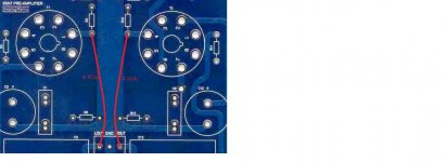
The board is set up quite nicely to try this - see attached, I can use the output terminal block for the one lead of the resistor, then run it the other lead back to the grid side of R2 and R10.
In relation to the gain calculation - if we start at 470k as suggested by Mel B, this gives a gain of 470k/1.2k = 391.6 - how is this converted to dB?
Attachments
You won't get 391.6 gain, and you probably don't want 1.2k input impedance.
The gain is limited by the open loop gain of around mu - 15-20?. 470k plus 1.2k will mean almost no feedback at all. You could try 470k feedback and 120k grid resistor. Assuming an open loop gain of 15 you will get a closed-loop gain of 15/(1+15x120/470)=3.1, from the usual feedback equation.
To convert to dB, take the base 10 logarithm, then multiply by 20. (3.1 -> 9.8dB)
You could try 470k feedback and 120k grid resistor. Assuming an open loop gain of 15 you will get a closed-loop gain of 15/(1+15x120/470)=3.1, from the usual feedback equation.
To convert to dB, take the base 10 logarithm, then multiply by 20. (3.1 -> 9.8dB)
I finally got around to testing this recommendation, with good results.
In fact, the sound improves even further when the cathode bypass capacitors are removed. This drops gain to mu/2, then with the added feedback the mu is more akin to mu/3.
I also changed the tube to PCC88/7DJ8 as the filament voltage was very high - 7.1Vac! This necessitated dropping the cathode resistors down to 420R, and a plate voltage of 90v (as per datasheet's 'typical operation spec'). The bias is now 2.1V.
On a separate note, the resistors in this circuit are all very tightly matched, however the left channel cathode resistor reads 2.1V, whereas the right channel reads 2.3v. What would cause this issue? Could it be poorly matched tubes?
Last edited:
That is good to hear.
PSRR has not audibly suffered despite the cathode bypass resistor removal.
Is 2v an appropriate bias level for the PCC88? I can't find it in the datasheet.
Certainly the PCC88 gives a much lower output impedance than the 6SN7.
Whoah boy was the original cicruit flawed - it is almost as if the designer simply wanted to use a 6SN7 at all costs rather than looking at the science of the situations. It is sounding like a much more 'level headed' linestage after all of the modifications you all kindly suggested!
lordearl - do you have any tweeter noise? Hash, white noise....dunno about its name. My 6SN7 SRPP preamp has it and I'm having a lot of trouble getting rid of it. I have stoppers everywhere but the noise is not stopped.
My filaments are floating with a 0.1uF cap to ground, I got rid of the bypass caps (same thing you did). I also have a switch that adds 11dB of feedback (47K/ 390K) this attenuates somewhat the noise but not enough. My grounding is perfect. I'm out of ideas. Desperate, I'm about to buy an oscilloscope but the reading manual is too big. Sometimes, I feel like crying - I'm an useless audio builder.
My filaments are floating with a 0.1uF cap to ground, I got rid of the bypass caps (same thing you did). I also have a switch that adds 11dB of feedback (47K/ 390K) this attenuates somewhat the noise but not enough. My grounding is perfect. I'm out of ideas. Desperate, I'm about to buy an oscilloscope but the reading manual is too big. Sometimes, I feel like crying - I'm an useless audio builder.
- Status
- This old topic is closed. If you want to reopen this topic, contact a moderator using the "Report Post" button.
- Home
- Amplifiers
- Tubes / Valves
- 6SN7 SRPP - oscillating dc offset