Back to the tubes: 300B PSE monoblocks
Back to the tubes after 25 years (from 1985 up to 1990 i was service technician of the famous Counterpoint from which i don't remember nothing and i lost all service plans).
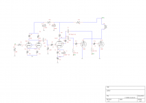
Now, after the request of a friend, i decided to build two single ended monoblocks, without feedback with two 300B tubes connected in parallel at the output. I led in this solution because remembers me something from the past. So, this amplifier classified in the "Parallel Single Ended" sub-category. I did it, because the woofers of my friend's speakers are loaded from the back with a folded horn of significant length and many times folded. That is a heavy load in Low frequencies. So I considered that the amplifier needs special care in output power. With two paralleled 300B, the output power could be in the region of 18 - 20 Watts.
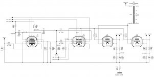
My circuit is based on this of Andy Grove designer of Audio Note: "300BSEi integrated stereo amplifier". This amplifier was offered as kit from a company. The circuit is the upgraded version. I did the required modifications for a power amplifier: The input selection switch and the volume pot have been removed and replaced from a single 100K resistor. I added some other parts so as the two 300B can be driven from the intermediate tube 5687. We calculated the output transformer primary at 1500 Ohms and the core at 100 Watts.
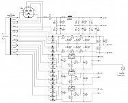
If you have the kindness: could you take a look on schematics of Power supply and amplifier channel?
1) The input sensitivity is given at 350mV and this is some low, what could I change in EF86 circuitry to increase the sensitivity at 1V rms?
2) Has the output transformer primary winding the correct resistance? 1500 Ohms are correct?
3) I think that 460Vdc is some big for the plates of 300B output tubes, i've read that their max Vp is from 400 up to 450 Vdc.
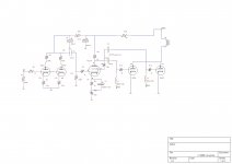
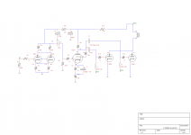
Any other advise, comment, correction will be much appreciated. I attach the schematics both as jpeg and for better resolution as pdf.
Back to the tubes after 25 years (from 1985 up to 1990 i was service technician of the famous Counterpoint from which i don't remember nothing and i lost all service plans).
Now, after the request of a friend, i decided to build two single ended monoblocks, without feedback with two 300B tubes connected in parallel at the output. I led in this solution because remembers me something from the past. So, this amplifier classified in the "Parallel Single Ended" sub-category. I did it, because the woofers of my friend's speakers are loaded from the back with a folded horn of significant length and many times folded. That is a heavy load in Low frequencies. So I considered that the amplifier needs special care in output power. With two paralleled 300B, the output power could be in the region of 18 - 20 Watts.
My circuit is based on this of Andy Grove designer of Audio Note: "300BSEi integrated stereo amplifier". This amplifier was offered as kit from a company. The circuit is the upgraded version. I did the required modifications for a power amplifier: The input selection switch and the volume pot have been removed and replaced from a single 100K resistor. I added some other parts so as the two 300B can be driven from the intermediate tube 5687. We calculated the output transformer primary at 1500 Ohms and the core at 100 Watts.
If you have the kindness: could you take a look on schematics of Power supply and amplifier channel?
1) The input sensitivity is given at 350mV and this is some low, what could I change in EF86 circuitry to increase the sensitivity at 1V rms?
2) Has the output transformer primary winding the correct resistance? 1500 Ohms are correct?
3) I think that 460Vdc is some big for the plates of 300B output tubes, i've read that their max Vp is from 400 up to 450 Vdc.
Any other advise, comment, correction will be much appreciated. I attach the schematics both as jpeg and for better resolution as pdf.
Attachments
Last edited:
300B tubes spec.
Hello,
I located the EML website with 300B tube spec. Emission Labs - Introduction
The "standard" 300B tubes run at 450V maximum rating there, but the bigger tubes mentioned below got a higher maximum voltage. From 550V-650V.
300B-XLS
320B-XLS
520B
1605
These tubes looks like they need higher heater current, from 1.5A-2.1A range.
-join-
Last edited:
1) The input sensitivity is given at 350mV and this is some low, what could I change in EF86 circuitry to increase the sensitivity at 1V rms?
2) Has the output transformer primary winding the correct resistance? 1500 Ohms are correct?
3) I think that 460Vdc is some big for the plates of 300B output tubes, i've read that their max Vp is from 400 up to 450 Vdc.
1) If you remove the input stage's cathode bypass capacitor (C20) that'll put you in the right ballbark. This poor stage is working very hard anyway, and can use the degeneration to help linearity.
2) Yes.
3) Only (a little less than) 400 volts appears across the 300B's. Some of the supply is lost across the cathode resistors. You should be fine.
All good fortune,
Chris
Thanks a lot Chris for the reply, suggestion and the wish for success. Before this, my friend informed me that the output of his tube preamplifier is 300mV. I came across some other tube preamplifiers and it seems that the level of 0.3V at output is very often used. I was a bit confused because in all of my "sand" preamp projects either implemented with ICs or discrettes, the usual output is from 1 to 2 Vrms. So, no reason to change the input sensitivity.
Simply, i will take a most carefull look on EF86 datasheet (this of Philips is very explanatory) to check transconductance, resistor values and operating points to obtain the best possible linearity. Though i think that the calculated values by Andy Grove should be correct.
I will be back with conclusions.
Thanks again.
Chris, after a careful looking at the EF86 datasheet, values of plate and grid resistors seems to be very well calculated in conjuction with capacitors to keep the tube in its linear operating region. Transconductance degeneration resistor should be correct and Cathode is also biased at the correct operating point.This poor stage is working very hard anyway, and can use the degeneration to help linearity.
Chris
I can percieve what you mean by saying "poor stage". It is unusuall the use of a pentode at the input stage which results in increase of transconductance. The most usual practice is the use of two cascaded triodes. I told you that this design is of Andy Groves who claims that the sound colouration is very vigorous using cascaded tubes while the use of a single tube in input gives a more balanced colouration. For that reason in all of his designs he uses a single pentode in input. I have seen enough schematics that make use of two cascaded triodes ECC802S Tesla NOS and concretely with some form of feedback from the output, i.e. from the secondary of output transformer! What is the profit of a single ended tube amplifier with feedback? More voltage gain in the cost of a bandwidth depending on the speaker impedance? I can percieve the reason of Andy Grove decision. Is the simplicity of circuit that gives a better tonality, that is exactly what makes people to turn in tubes. With tubes we can built amplifiers with very few parts in the signal path. And the increased 2nd harmonic that sounds very nice in the human ears.
In solid state designs we have resolved many issues. For example by the use of 4 pairs of output transistors we can obtain an amazing low output impedance, thereby amplifier is almost independed from speaker load variations. I still believe that the bass reproduction is more powerfull and very tight compared to tubes. Class A operation in solid state is less or more past. The latest improvement in solid state amplifiers is the true symmetrical designs (known also in old designers as bridging the bridges). With very low supply rails up to +/-35V (this offers possibility of using all "Super BETA" small signal and medium power tranies). Using this practice, I obtained a 2 X 150 Wrms / 8 Ohm amplifier implemented at whole with BJTs with SNR greater than 105dB/1W/8Ω and linear bandwidth up to 100KHz at full power/8Ω load. Its only drawback is that 2nd harmonic = -110dB/1W, so is inaudible!
Thanks again for advices and confirmation.
Hello again Chris1) If you remove the input stage's cathode bypass capacitor (C20) that'll put you in the right ballbark
Just one question more! (though i think you have finished with me, anything you had to say you said and that proves that you are very well experienced designer and above all a wise man).
My question is clearly technical and nothing more:
I had the impression that electrolytics C20, C22 and C23 offer some form of bootstrap. You said that C20 is a cathode bypass capacitor. Why this? I am almost novice with tubes and i allways try to emulate them with transistors to understand the operation of circuit.
Thank you so much.
You said that C20 is a cathode bypass capacitor. Why this?
Because it allows a DC voltage at the cathode (the bias for the tube) while being a short to AC. If you remove it, the AC signal is forced through the cathode resistor and you have local degeneration (negative feedback). No different than transistor circuit.
http://academic.reed.edu/physics/courses/Physics331.f08/pdf/Lab2_handout.pdf
Last edited:
Hello dgtaBecause it allows a DC voltage at the cathode (the bias for the tube) while being a short to AC. If you remove it, the AC signal is forced through the cathode resistor and you have local degeneration (negative feedback). No different than transistor circuit.
http://academic.reed.edu/physics/courses/Physics331.f08/pdf/Lab2_handout.pdf
Thank you so much for your informations, you are very kind. Meanwhile, i found my old book from the time of my studies (1977 - 1982) and helped me a lot! BTW, i read the piece of the book you attached for me; to my big surprise, i found that many of diagrams of Greek book are exactly same like the American book! The main difference of my book is that the author makes extensive use of imaginary numbers, so many quadratic equations and extensive use of Thevenin - Norton equivalence circuits and quadrupole equivalents.
The following, simply for the story:
So, EF86 (V1) is connected as common cathode amplifier (equivalent of a NPN transistor connected as common emitter amplifier) therefore is a Voltage Gain Stage (or commonly known as VAS with transistors). Capacitor C21 (15nF) ensures the "AC coupling" to the next stage, while C20 (220μF) ensures the "AC decoupling" of any AC component from cathode which developed from the variable anode (plate) current that follows the input stimulus applied on grid. Because "common cathode" means that the cathode resistor R27 (2K2) is common for the input and output part of this stage. So, any AC component accross R27 would affect the voltage of input signal. That is the job of C20, simply you refer it as "bypass capacitor" and i know it as "decoupling capacitor"! What a messing for nothing!
As you mentioned, the same is in effect for the emitter resistor of a transistor connected as common emitter. That is true, but you know by sure, that is the old fashioned method. From the 70s the voltage amplifier stage of an amplifier implemented with transistors is "DC coupled" to the next stage which is a symmetrical stage composed from driver transistors connected as emitter followers. Their emitter resistors are connected in output rail offering thus null of any DC component. In the VAS transistor also is not used any decoupling (or bypass) capacitor across the emitter resistor, the input stimulus is isolated by the well known LTP pair of transistors that forms a difference amplifier. Moreover, in all modern designs current mirrors, constant current sources and thermal compensation circuits ensures bias stability and correct impedance matching between all stages.
By the chance given, as we discuss here for solid state and tubes, a reference in FETs is usefull. The characteristic curves of a n-channel J-FET used as voltage amplifier, are very simillar to those of a pentode tube. If we take into account that in the input of FET does not flows current and that its input impedance is very high the similarity with tubes is growing-up. Another one similarity of FETs with tubes, is their increased 2nd harmonic. I haven't built nothing with FETs, but i tried them enough times in simulator a circuit composed either by J-FETS or BJTs to make a comparison. Indeed, the 2nd harmonic produced by J-FETs is by 10 to 20dB greater than this produced by BJTs. That leds in a bigger THD.
That explains why clear tube amplifiers are classified in the first place of HI-END, tubes mixed with MOSFET in the second place, and clear MOSFET amplifiers in the third place. Transistor amplifiers are not included in classification!
Closing this post, i have to refer a very interesting comparison between low power triodes and pentodes. Pentodes offer very big "μ" (amplification factor), "ρ" (dynamic internal resistance or simply "Ri") and gm (transconductance) compared to triodes. These 3 parameters offer the possibility of building with pentodes small signal amplification stages with big possibilities, that could not be easily obtained with the use of a triode. Additionaly a pentode has bigger capability to amplify high frequency signals than a triode. Screen grid and Suppresor grid create a very strong shield between input and output while, at the same time, reduces significantly the parasitic capacitance "Cga" and consequently the "Miller phenomena". So pentode has no need of special precautions in the high frequencies region. Its only drawback is that is not so linear like a triode. But the correct choice of its operating point combined with input signals of small amplitude can ensure a simillar linearity like this of triode.
Another one interesting point is that pentode due to its high internal resistance, behaves - from a physical point of view - mostly like a constant current source and so like a NORTON equivalent. If i am wrong, please correct me but i think that in a same way works and the VAS transistor in BJT implemented amplifiers.
In schematic, capacitor C19 (470nF) connected between "screen grid" and GND thru C20 - if i am wrong please correct me - i suppose that ensures the decoupling of any AC component that can affect its stability in a same manner like the C20 "cathode AC decoupling capacitor". It also be noted that the anode resistor R25 (200K) in reality is composed from two 100K resistors connected in series. This ensures a lower voltage drop accross each resistor the half of Vbb voltage (+400V) which is too high.
Summarizing, i can say that the way of thinking and the spots mentioned by Andy Grove are better understandable by me now.
Thank you again for your help to introduce me in the "tube way".
Last edited:
The two triodes are connected in parallel. Both grids, both anodes and both cathodes. It's been working for 6 years now. The advantage is a bit less noise (3 dB) from what I can gather. I did it because I like the 6SN7 and there was a triode left over. Might as well take advantage of the noise reduction and "lower internal resistance" which may or may not be discernible here.
Schematic edit...... 6SN7 anodes wired together at socket, grids wired together at socket, and cathodes wired together at socket. Sorry bout that..it still would have worked though me thinks.
Hi Mel
Though i am novice with tubes, i know some things about electronic circuits. So, please give me a chance to explain you what dgta means:
Let's start from 3 basic principles:
1) The conventional direction of current flow, is ALLWAYS from a point with high potential to a point with lower potential. Though electrons - which are the only physical carriers of electric energy - move in the inverse direction, the so called "true direction of current flow".
2) The anode (plate) of a tube is allways connected at a higher potentional than cathode. Tube cathode is allways connected at a lower potential point (i.e. to GND thru a bias resistor). So the current flow direction is from anode to cathode.
3) The grid is the "manager" of the current flow from anode to cathode. The input signal is applied on grid.
So the voltage of grid follows exactly the voltage swing of input signal and that causes a variable current that flows from anode to cathode which of the level is in accordance with the input signal. This current variation keeps just the information of the input signal but it is useless for the grid of the next tube. It should be firstly "translated" to a voltage swing. For that reason exactly, a "resistor - translator" is connected at the anode circuit (actually R5 - R6 on your schematic forms this resistor). The voltage drop accross this resistor that is caused from the current flow thru anode to cathode, is the "translator" from current to voltage swing. But the voltage drop point is found between resistor and anode. In the upper terminal of resistor there is no voltage drop. Get your multimeter and connect its negative lead to GND. Set the rotary switch to Volt-AC position. Put a music signal in input, and place the positive lead on the anode. You will see a continuously variable AC voltage on the display of multimeter. Place now the positive lead at the upper terminal of e.g. R5. Normally, you should get just a constant voltage indication. But this is not in effect on your circuit! You have placed this R16 between B+ voltage point and R5! So R16 can give you a simillar voltage drop - though very small due to the small value of R16 = 4.7K - that follows the input signal swing!
 Amazing, ha?
  For that reason exactly i believe you, i.e. that your amplifier is by some way working, though the AC coupling capacitor C2 to the next stage is connected at the wrong point: between R16 - R5/R6. If you connect the capacitor exactly at the anode terminal, then you should get a greater voltage drop because parallel connected R5-R6 form a higher value resistor = 50KOhms. So a greater voltage swing to the next stage consequently a far better sound quality.
 That is what try to say you dgta.
At the end, is not so tiring for you an effort to make this small experiment!
Last edited:
don't forget that your output transformer drops dc voltage also, take this in consideration when designing for B+, plate current x dc resistance of opt = transformer drop....this can be significant if you have an opt with high primary dc resistance....
so B+ minus cathode bias drop, minus primary output traffo drop equals your actual plate voltage.....
so B+ minus cathode bias drop, minus primary output traffo drop equals your actual plate voltage.....
You guys don't get it. Two triodes strapped together. Wire it up and try it.
This guy has no less than five strapped together:
Parallel Connection of Triodes
This guy has no less than five strapped together:
Parallel Connection of Triodes
Here is a schematic from an incredibly popular guitar amplifier with the first triode wired in parallel:
Prowess Amplifiers - Matchless Schematics Look at the Matchless Clubman
Prowess Amplifiers - Matchless Schematics Look at the Matchless Clubman
- Status
- This old topic is closed. If you want to reopen this topic, contact a moderator using the "Report Post" button.
- Home
- Amplifiers
- Tubes / Valves
- Back to the tubes