Check the resistance across various pairs of wires to determine what's connected to what. If three wires show resistance between them, it's center tapped; determine where the ends are and where the center tap is (the center tap has roughly equal resistance to each end, and the ends have roughly double the resistance to each other compared to the center tap.
I usually connect the meter negative to one wire and test all the remaining wires with the positive lead. Then move the negative to a new wire and repeat until you've exhausted all of your combinations. Write down the various values, determine if any are center tapped.
Can you list the wire colors? If it's following any convention, that may get you far along quickly.
Once you've got your various R's you can then think about applying voltage. Do you have access to a variac or other means to limit the primary voltage/current?
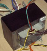
I tried to post a pic but had no luck. Here are the wire colors.
There are two white wire,s two brown wire,s and two green wire,s. All of these are very heavy guage (8ga)
The rest are smaller.
2x blue
2x yellow
2x orange
2x grey
1pr grn/red
1pr red/red,yellow
1 pr yel/blk
1 single purple.
There are two white wire,s two brown wire,s and two green wire,s. All of these are very heavy guage (8ga)
The rest are smaller.
2x blue
2x yellow
2x orange
2x grey
1pr grn/red
1pr red/red,yellow
1 pr yel/blk
1 single purple.
Ok here is what I get
rd/rd,yel 21ohm
rd or rd,yel across ppl 42ohm
yl/yl 8.0 ohm
rd/grn 2.5 ohm
all others 1.5 ohm
I guess I'm confused about your resistance readings.......
what does rd or rd,yel across ppl 42ohm mean?
If red to purple is 42 ohms and red/yellow to purple is 42 ohms and red-red/yellow is 21 ohms, then purple can't be the CT......unless I'm missing something.....

If purple is the CT, then some other pair needs to be 84 ohms....
although it sounds like end to CT =21 ohms and end to end is 42 ohms, which are reasonable numbers.
Ok, sounds like you got the CT figured out on the secondary. Is this a confirmed high voltage tube transformer (as opposed to a 12V or 18V etc secondary.)?
Red/yellow is a common CT color. Green is a typical heater winding (6.3V) and yellow is typical for a 5V winding for a rectifier filament.
What are "all others" above? Color and resistance? Are there any black or white leads? Do you have any idea what the secondary high voltage should be (roughly)?
Are there any other triples that are center tapped?
Do you have any other low voltage transformers? You may be able to use one to test this in safer manner than plugging into the mains. A variac is extremely handy for this. I've never used the lightbulb trick but it should work fine.
A picture would go a long way....
If you are using windows posting a pic is easy (I imagine that it's easy with a Mac too; I just don't know how to do that)
Snap a good close up picture, stick the camera card in the computer, right click on the pic and open with paint. Once in paint, click the resize button and shrink the image to say 40-50% of orig size, then save. Right click on the down-sized image and select properties to view the reduced file size. Once it's smaller than 200K, you can use the "manage attachments" button when you are posting to attach the pic here.
Edit: I just re-read your post 7 above. What are the resistances between the "other" colors and are any of them center tapped? Specifically any white, black, brown, blue........
White and black are common primary (mains) colors for US, Brown/blue are common primary colors everywhere (int'l).....Is the transformer old?
Last edited:
What I would do is get a little 10 Volt AC wall-wart (10V or something near 10V). Cut the connector off the output wire. Jumper the wall-wart to the leads that you think are the primary wires. Measure the voltage of all the secondary combinations, multiply these readings by the ratio of line voltage to wall-wart voltage.
Do you have any other low voltage transformers? You may be able to use one to test this in safer manner than plugging into the mains.
What I would do is get a little 10 Volt AC wall-wart (10V or something near 10V). Cut the connector off the output wire. Jumper the wall-wart to the leads that you think are the primary wires. Measure the voltage of all the secondary combinations, multiply these readings by the ratio of line voltage to wall-wart voltage.
exactly...Kendt-Note that you need an AC wall-wart or other small transformer...DC won't work (obviously)
- Status
- This old topic is closed. If you want to reopen this topic, contact a moderator using the "Report Post" button.
- Home
- Amplifiers
- Tubes / Valves
- help with power tranny