Is anything else center tapped?
If you can feed it with something less (perhaps way less) voltage than 115VAC mains, you'll have a much greater chance to keep the smoke in. Can you wire up an in-line fuse, say 1 amp in series with the mains?
Do you have any small step down transformers?
You could also entertain connecting mains voltage across the ends of your center tap already identified with a small fuse, say 500ma, then measure other voltages; they should be less than mains voltage if it's a tube transformer and you've identified the CT B+ taps...
Then you can determine the mains taps by the ratio of voltages.
The car inverter may be a reasonable idea to limit mains current.....if it's a small one with a fuse..")
If you can feed it with something less (perhaps way less) voltage than 115VAC mains, you'll have a much greater chance to keep the smoke in. Can you wire up an in-line fuse, say 1 amp in series with the mains?
Do you have any small step down transformers?
You could also entertain connecting mains voltage across the ends of your center tap already identified with a small fuse, say 500ma, then measure other voltages; they should be less than mains voltage if it's a tube transformer and you've identified the CT B+ taps...
Then you can determine the mains taps by the ratio of voltages.
The car inverter may be a reasonable idea to limit mains current.....if it's a small one with a fuse..
Last edited:
There is only one set of c/t wires. It is a tube amp transformer, I bought it some time ago for that purpose. I have a 60w dc/ac inverter that has a fuse. It wont handle much current so if anything goes awry it should blow straight away. Should i assume the heaviest guage wires are the primary's since they would have to be able to carry the full load of the tranny under operation.
Should i assume the heaviest guage wires are the primary's since they would have to be able to carry the full load of the tranny under operation.
Maybe, maybe not.......filament windings need to put out 6A or more sometimes, depending on the number of tubes they need to light up, so they can be quite large conductors. If it's old, mains conductors were usually black.
As you are probably aware by now, the mains windings usually have very low resistance.
I could be wrong, but I don't think you can do too much damage by connecting your low power inverter (with a small fuse) across the high voltage secondaries and measure other taps. Then it's just figuring out voltage ratios with a calculator. All the other voltages will be less (perhaps much less) than mains voltage. If that works, you can also connect the inverter output across the CT to one end, that should double all of the other voltages and start to paint a clearer picture of what you've got. After that you'll probably have a good idea where the mains conductors are. A variac makes this a no-brainer.......guess at the mains leads, connect of few volt meters across the other windings, and slowly bring up the voltage to say 10V, then see if the other voltages are what you expect before continuing up.
One thing that you don't want to do is (accidentally) connect mains voltage across a filament winding meant for 5V or 6.3V, as that will make the HV output way too high, perhaps shorting the windings and releasing acrid smoke.
If the transformer buzzes audibly, you are probably not connected correctly...
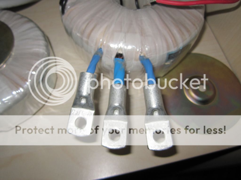
Based on the pic, if you had a way to apply some low voltage AC, I'd guess the brown conductors are the primary leads.....just a guess....
- Status
- This old topic is closed. If you want to reopen this topic, contact a moderator using the "Report Post" button.