Better?
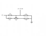
nope. If the wiper lifts, your tubes are "full on". Study the circuit in post #29 or post #31, At least one bias circuit resistor needs to connect to the tube grid without going through the pot wiper. That way, if the pot goes open, the grid is still connected to the -ve bias voltage.
Last edited:
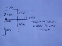
And the 37k resistor isn't between the supply and the grid even if the wiper lifts? If the wiper lifts the 37k/22k voltage divider comes into play alone. The output voltage from which is about 27 volts not zero? (Which needs tweaking as it is a bit too high.)
Sorry, yes. What you have works.....had to turn my head sideways to see it....

I think your R values need tweaking though. I would shoot for an adjustment of about -20V to -35V or so on the grid.
Last edited:
Kevin: Here is what I came up with......please check the math. It appears a 10K pot does not give much voltage adjustment unless lots of bias current is flowing to ground. This circuit is using between 2.1-2.8 ma of bias current to ground.
Attachments
Last edited:
Thanks guys, I'm glad I finally got it right. I already have some nice Bourns 10k PCB mount pots I may return them for 20k if Digikey has them. I'm using an Antek AN0124 transformer here 2 x 24 volts at 210ma. I'm going to build the boards and the rectifier and see what I get for voltage. Then put in the values I need. The bias will drw something like .001125 of current so the transformer output should be near peak.
Hello Again All,
Can anyone tell me what wattage the 100ohm pot in the CCS needs to be? And is it just connected on the one end and the wiper? And does all the DC current go to ground through the lower tubes grid?
Kevin
I used a small bourns trimpot.....just connected at one end and the wiper.
Hey All,
I'm finally getting started on my music machine(s). I'm going to use Eico ST70 iron with a second power transformer.
I plan to have Heyboer build me another power transformer so I can build a pair of 6550C MM monoblocks. They'll have 438 volts of B+ at 94ma per 6550. With 188ma for the outputs and 24ma for the CCS 6GK5's, at 212ma the power transformer will have some nice headroom. The amp should produce a little over 30 watts. With the Z out of 4k the 16 ohm becomes 8 and the 8 ohm becomes 4.
Is there anything I can do to get a little more drive out of the 6gk5's? More current? Higher B+?
Kevin
Is there anything I can do to get a little more drive out of the 6gk5's? More current? Higher B+?
Kevin
Mosfet followers......look at Sgregory's Opus project or Chrish's 6L6GC AB2 project. You can probably drop the entire mosfet stage from either of these right into the MM.
http://www.diyaudio.com/forums/tubes-valves/161702-opus-5-0-modern-mullard.html
http://www.diyaudio.com/forums/tubes-valves/133034-6l6gc-ab2-amp.html
Boywonder,
Read the thread for the Opus, couldn't find the 6L6GC amp. The power supply and the mosfets seem a little more complicated than I'm ready to get into just yet. Is there any reason I couldn't use a tube cathode follower? Would 6CG7 be a good candidate?
Kevin
I imagine that you could use a tube cathode follower......mosfet followers are pretty straightforward, you just need an additional power supply. I'm no expert here, but I believe the negative rail needs to exceed the -ve bias voltage with a little headroom, and the +ve rail allows some A2 operation. I think you need a little +ve voltage for the mosfet drain to provide some headroom even for AB1 operation.
Late in the 6L6GC AB2 thread there is discussion about KT88 operation.
Are you planning on using a preamp? You still have limited voltage swing of the 6GK5 to deal with when driving 6550/KT88. Since an LTP gives you 1/2 mu, you can only swing about +/- 39V or so with the 6GK5. To fully drive 6550's/KT88's you need around +/-50V or so.
Using a higher mu LTP will give more voltage swing and using a cathode follower or a mosfet follower will provide the current needed, although the amp will no longer be a MM.
Hey,
I got an email from John Broskie and something he said as well your posts got me thinking. Am I correct in thinking that to drive a tube to full output you have to swing plus or minus the bias voltage on the grid?
Yes. For AB1 operation, you need to swing +/- the grid bias voltage. For AB2, you need a little more, so that the grid voltage can go positive.
Folks usually want the small signal tubes to drive more volts and current than the outputs require for some robustness. Keep in mind that if your input/LTP stage can swing more voltage than the outputs require, the small tube's output will be more linear, ie less distortion.
Sovtek 6B4G
Eli Duttman
The 6BGs from the Siberian Shop rate to be Soviet NOS and lack the toughness of current production Sovtek 6B4Gs. AFAIK, New Sensor uses the same anode stamping for 6B4Gs and 300Bs, for economy of scale. It's no wonder that their 6B4Gs are tough. __________________
Eli D.
I see from the Sovtek data on the 6B4g and 2A3 Sovtek claims only 15 watts.
Compared to the Single plate RCA 2A3 also 15 watts: i have the Sovtek plates are much larger. I notice the Shuguang also only cliam 15 watts for their large 2A3's
Why?
Thanks
Phil
Attachments
- Status
- This old topic is closed. If you want to reopen this topic, contact a moderator using the "Report Post" button.
- Home
- Amplifiers
- Tubes / Valves
- Musical Machine (triode PP EL34) question(s)