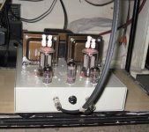
A single ended amp might be interesting. This amp looks nice 829B Amplifier I think Tony knows something about it as he was mentioned on the page as contributor.
829b in single ended is iffy, you have to have lots of those to choose which are colely matched, otherwise red plating can happen...
the 5894 with its single cathode construction is better for single ended, i have such an amp made using those 5894's
the 5894 with its single cathode construction is better for single ended, i have such an amp made using those 5894's
Attachments
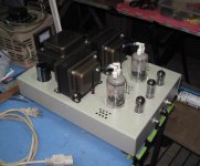
Interesting Tony, how do you like it? How does it perform?
very nice indeed, on my 90db floorstanders, very good to my ears...
sure, but i will have to download it first, in my head....
i have the amp with me now and the owner asks me to convert to push-pull using the same set of tubes, only the OPT will be replaced....will pm you once i have it...
edit: i found a sketch in my hard drive...
i have the amp with me now and the owner asks me to convert to push-pull using the same set of tubes, only the OPT will be replaced....will pm you once i have it...
edit: i found a sketch in my hard drive...
Attachments
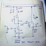
since he is now very happy with the 2a3 set i made for him,
i convinced him to make a push pull tube amp, so that he can swap amps once in a while...
the tubes will change roles, the 12at7 wll be used at LTP phase splitter and the 6CG7 as input voltage amp...
just a change in roles for the small tubes and a change in OPT, the new OPT will smaller..
i convinced him to make a push pull tube amp, so that he can swap amps once in a while...
the tubes will change roles, the 12at7 wll be used at LTP phase splitter and the 6CG7 as input voltage amp...
just a change in roles for the small tubes and a change in OPT, the new OPT will smaller..
I see, I purchased some new power tubes. One set is said to be the equivalent of the 5894
here they are here. 1x ZAERIX RS1009 TUBE | eBay I have heard they run very hot do you find this to be the case? I also purchased a set of these 829b equivalents called srs4453 here is the auction SRS4453 – 829B - GU29 – 2x RFT Rohren-Tubes-Valves NOS/NIB | eBay. I have to get my amp up and running but i was planning on using the srs4453. Seems you prefer the rs1009/5894 tubes yes?
here they are here. 1x ZAERIX RS1009 TUBE | eBay I have heard they run very hot do you find this to be the case? I also purchased a set of these 829b equivalents called srs4453 here is the auction SRS4453 – 829B - GU29 – 2x RFT Rohren-Tubes-Valves NOS/NIB | eBay. I have to get my amp up and running but i was planning on using the srs4453. Seems you prefer the rs1009/5894 tubes yes?
Digging up this old thread as I have some info that relates to this amp. Just got one on my bench for repair- blows fuses on power up.
What rating is the input fuse?
This one had 2A. Inrush current was massive, yet all power supply components test fine and unit plays stable for hours after brought up slowly on a Variac & pulls just over 1A when operating. Reducing first filter cap from 270µF to 47µF in the plate supply greatly reduced inrush. Added a thermistor (CL 80) to knock down the 10+ percent dc voltages I’m measuring. The AC switch on this one was wired on the neutral side. Switched neutral (AKA earth, return or ground) wires are a hazard, so I rewired it, putting the switch after the fuse on the hot side.
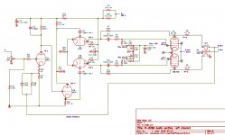
There seems to be some variations in the schematic. To set bias and balance, I just measure Vdrop across the resistors in series with each plate lead. Mine came with 1.0 Ω sense R's, target for 25mA each section. Added 1 ohm 1/2W in series with the cathodes as a fuse resistor for safety.
Some very good info on this amp with the correct schematic, attached.
Analog Sauce: The Audioromy M828-A – Engineering Radio
What rating is the input fuse?
This one had 2A. Inrush current was massive, yet all power supply components test fine and unit plays stable for hours after brought up slowly on a Variac & pulls just over 1A when operating. Reducing first filter cap from 270µF to 47µF in the plate supply greatly reduced inrush. Added a thermistor (CL 80) to knock down the 10+ percent dc voltages I’m measuring. The AC switch on this one was wired on the neutral side. Switched neutral (AKA earth, return or ground) wires are a hazard, so I rewired it, putting the switch after the fuse on the hot side.
There seems to be some variations in the schematic. To set bias and balance, I just measure Vdrop across the resistors in series with each plate lead. Mine came with 1.0 Ω sense R's, target for 25mA each section. Added 1 ohm 1/2W in series with the cathodes as a fuse resistor for safety.
Some very good info on this amp with the correct schematic, attached.
Analog Sauce: The Audioromy M828-A – Engineering Radio
Attachments
Last edited:
kstlfido funny you should post this, I just found the same site last night.
I've got a M8282A that is waiting for me to troubleshoot. It started with intermittent pop and crackles. Now the pre tubes are not lighting up.
So I'll check the tubes first, then the psu, starting with the filament supply.
I've got a M8282A that is waiting for me to troubleshoot. It started with intermittent pop and crackles. Now the pre tubes are not lighting up.
So I'll check the tubes first, then the psu, starting with the filament supply.
- Status
- This old topic is closed. If you want to reopen this topic, contact a moderator using the "Report Post" button.
- Home
- Amplifiers
- Tubes / Valves
- Audioromy FU29 improvement and upgrades?