Hi ,
I have an VFD display of following type and as controller I have some samples of PT6311. I wanted to use them with MSP430 MCU of TI.
MSP430 is operating at 3.3V. I need arround -30V AC to drive this VFD's filament.
Can anyone help me on this???
What exactly is -30V AC? Either it has a polarity, or it is AC...

Rundmaus
Whoa, IIRC, the filament on VFD's is normally 3 volts, and -30 applied to the cathode to illuminate the segment.
Hey there,
for VFD as well as for other tubes, the (electron emitting) filament *is* the cathode.
But you are partly right, one has to distinguish between the voltage/current to heat the filament (probably a few volts) and the 'anode voltage' between the filament and the rest of the display - this will probably be the 30V mentioned.
A datasheet for the VFD would help!
Greetings,
Rundmaus
Hellow to all,
The unit I am building is getting its supply from DC wall adapter & it is better if I avoid usage of transformer.
I had came across some Chinese amplifier where I found this VFD & its driver IC.
There they had used two additional winding of 3V/0.3A,28V/0.2A. For my case,
I need some converter chip to generate those from 3.3V.
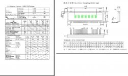
I had attached VFD datasheet on previous my post..but it was bigger then the size mentioned. Anyways attaching only the relevant pages in JPEG form.
The unit I am building is getting its supply from DC wall adapter & it is better if I avoid usage of transformer.
I had came across some Chinese amplifier where I found this VFD & its driver IC.
There they had used two additional winding of 3V/0.3A,28V/0.2A. For my case,
I need some converter chip to generate those from 3.3V.
I had attached VFD datasheet on previous my post
..but it was bigger then the size mentioned. Anyways attaching only the relevant pages in JPEG form.Attachments
Here's a link with some general info on driving VFD's.
Vacuum Fluorescent Display (VFD)
Vacuum Fluorescent Display (VFD)
You need a specialized chip. Something like these: Holtek Semiconductor - VFD Controller & Driver Series
I have a similar chip ... PT6311 but it is not a problem. Problem is generating the supply for VFD display & PT6311.
I know Maxim makes DC to DC converters. You can start from here VFD Grid/Anode Supply Using MAX6850-MAX6853 PUMP Output - Maxim
There are many many ways to skin this cat.
I built this clock based on an Atmega8 and a Soviet IV-18 (IW-18) VFD display.
It uses a simple capacitor multiplier from a 12V AC walwart for the Grid voltage.
Zegar i termometr na IW-18

Some circuits like Riad S Wahaby's inGrid use a PWM from the
microprocessor to generate the VFD voltage.
inGrid IV-18 VFD clock
Application notes and Y Series how to guides
Limor Fried (Lady Ada) has a very beautiful IW-18 clock, and has put
up comprehensive documentation on the processor driven converter.
http://www.ladyada.net/make/icetube/
http://www.ladyada.net/make/icetube/design.html

555 based boost converter...
Zegar VFD na lampie IW-18 [AVR] sid.devBlog();
MC34063 based converter -

PipeBOMB - zegar VFD,lampa IW18,Pilot, BlueTooth, sync. SNTP
I built this clock based on an Atmega8 and a Soviet IV-18 (IW-18) VFD display.
It uses a simple capacitor multiplier from a 12V AC walwart for the Grid voltage.
Zegar i termometr na IW-18
Some circuits like Riad S Wahaby's inGrid use a PWM from the
microprocessor to generate the VFD voltage.
inGrid IV-18 VFD clock
Application notes and Y Series how to guides
Limor Fried (Lady Ada) has a very beautiful IW-18 clock, and has put
up comprehensive documentation on the processor driven converter.
http://www.ladyada.net/make/icetube/
http://www.ladyada.net/make/icetube/design.html
555 based boost converter...
Zegar VFD na lampie IW-18 [AVR] sid.devBlog();
MC34063 based converter -
PipeBOMB - zegar VFD,lampa IW18,Pilot, BlueTooth, sync. SNTP
Last edited:
Sorry to pull up an old thread, you can keep it entirely solid-state without any transformers or coils. Using a power op-amp or audio amplifier IC, you can drive the filament AND a diode/capacitor ladder circuit at the same time, to power the VFD.
Drive the audio amplifier/power op-amp with a square wave generated by the micro, using the same timer as the one that does the multiplexing interrupt, this will keep things in sync and eliminate beat artifacts entirely.
The filament is coupled to the op-amp via capacitors, this will allow you to float the filament at wherever for cut-off.
If you wanted to keep filament voltage, and anode voltage independent, then you could built a boost circuit and a op-amp filament drive circuit seperate, and use 0C1A/0C1B both from the same timer. They are in sync, but independent adjustment PWM.
Last edited:
- Status
- This old topic is closed. If you want to reopen this topic, contact a moderator using the "Report Post" button.
- Home
- Amplifiers
- Tubes / Valves
- Need VFD display filament driver