Is there any available data sheet that shows output tubes' frequency response? I know the typical "describing" words that people use (EL84s are chimey, 6L6s are glassy, etc) but is there any data out there that can actually show a particular output tube would be better suited for a particular application (bass clarity for example). Just curious, thanks.
No, not really. The performance of an output stage is dependent on the tubes, the transformer, and the stage driving it. Without knowing all of those things, you can't predict performance. The "glassy," "chimey," "cloudy," "chocolatey" stuff about tubes is audiophile nonsense, as much as ascribing engine performance to specific types of main bearings. An amp's performance is far more dependent on overall design and execution than whether you used current production Lo Hung Dong 6V6 or 1953-vintage Achtungsbieremesse NOS EL84.
A 6V6 is good from DC to somewhere around 10MHz. An EL84 may go a bit higher, as it is smaller.
If output valves have any effect on perception of frequency response, this will be caused by distortion masquerading as frequency imbalance. Conclusion? Don't fully trust your ears, especially when your eyes know what you have changed.
If output valves have any effect on perception of frequency response, this will be caused by distortion masquerading as frequency imbalance. Conclusion? Don't fully trust your ears, especially when your eyes know what you have changed.
As mentioned by both SY and DF96, tubes themselves have relatively high bandwidth. I'll just add that it is the output transformer that forms the bandpass filter and dominates the frequency response.
The 'chime' and 'glass' character you mention is typical of guitar amp reviews, and the way a guitar amp responds is much more determined by overall design, and not what tubes in use.
The 'chime' and 'glass' character you mention is typical of guitar amp reviews, and the way a guitar amp responds is much more determined by overall design, and not what tubes in use.
A 6V6 is good from DC to somewhere around 10MHz.
At least. Many typical audio tubes are good to 20 or 30 MHz with proper RF circuit design, assuming that you are actually making an RF amp. The old Metal 6L6 will work on the 20 meter ham band (14 MHz) and put out considerable power. Even the worst type of tube should cover up to a few MHz, so frequency response of the tube itself is not a factor in an audio amp.
I know the typical "describing" words that people use
I have my own....from a guitar amp builders perspective.....6V6's were made to sing the blues but EL84's rock!
I have my own....from a guitar amp builders perspective.....6V6's were made to sing the blues but EL84's rock!
Or vice versa
 ?
?I don't think that output tubes, or any tube at all, will produce harmonic distortion in the audio frequency range. But, as told by the others before, non-harmonic distortion is different between the tube types. And this means different sonic perception by the listener or the musician.
Best regards!
I suspect this is not what you intended to say.Kay Pirinha said:I don't think that output tubes, or any tube at all, will produce harmonic distortion in the audio frequency range.
Is there any available data sheet that shows output tubes' frequency response? I know the typical "describing" words that people use (EL84s are chimey, 6L6s are glassy, etc) but is there any data out there that can actually show a particular output tube would be better suited for a particular application (bass clarity for example). Just curious, thanks.
The frequency response is dominated by that of the OPT. The LF pole is set by the magnetizing inductance and the DCR. The HP pole is dominated by the leakage inductance and parasitic cap as I recall. All of those depends on the winding style and materials chosen.
I actually put my OPT's on an HP 4194A impedance analyzer and had it calculate the parasitic components for me. Using those values in LTspice, the simulation predicted the LF and HF poles to within a few percent of the values I measured on the finished amp.
~Tom
At least. Many typical audio tubes are good to 20 or 30 MHz with proper RF circuit design, assuming that you are actually making an RF amp. The old Metal 6L6 will work on the 20 meter ham band (14 MHz) and put out considerable power. Even the worst type of tube should cover up to a few MHz, so frequency response of the tube itself is not a factor in an audio amp.
No need to add proof to this but for exmple the gu48 has been used with success in audio amps and yet was designed for RF heating. 80mhz max if I recall correctly and no significant adavantage comes from this characteristic in audio applications over smaller tubes.
Last edited:
The frequency response is dominated by that of the OPT.
In some of my amps it is the only frequency dependent item in the signal chain. True there is one coupling cap, but it's pole is below 1Hz. There is no feedback otherwise the amp would be unstable.
I have been working on a monster sized breadboard that uses Plitron toroidal OPT's in P-P. The OPT's are rated for 400 watts at 20 Hz. The upper 3db point is 75KHz. Any tube that I have tried in it is capable of a frequency response of 5Hz (lower measurement limit) to 40KHz +/- 1db. It's just that some tubes are a little more powerful than others. It takes careful circuit design to make an amplifier thats not dependent on the tube type.
With smaller OPT's the tube's internal impedance will affect the frequency response at both ends of the curve. A given OPT will usually have a broader frequency response when driven by a lower impedance source. Every tube has a characteristic impedance that varies with the amount of current flowing through it. Negative feedback can be used to lower a tube's internal impedance.
Every tube will have an internal capacitance associated with it. This will affect how well it performs in a circuit. The tube or mosfet that is driving the output stage must have a low source impedance for it not to be affected by the output tubes capacitances.
A typical amplifier design with average transformers will exhibit different frequency response with different tubes. The differences will be dependent on the circuit design and OPT quality.
Or vice versa
I don't think that output tubes, or any tube at all, will produce harmonic distortion in the audio frequency range. But, as told by the others before, non-harmonic distortion is different between the tube types. And this means different sonic perception by the listener or the musician.
Best regards!
Good one.... with respect to SY's comment,"1953-vintage Achtungsbieremesse NOS EL84".
Hav e you tried it ? same flag of convenience.
richy
I have been working on a monster sized breadboard that uses Plitron toroidal OPT's in P-P. The OPT's are rated for 400 watts at 20 Hz.
So in the end you are going down the large tube - enormous OPT road yourself?
I probably will have to go for a 2000va core OPT. Reduced frequency response but should still adequately cover the 20 hz 20 khz range.
I suspect this is not what you intended to say.
You're right, thank you. I meant linear distortion vs. non-linear distortion.
Best regards!
My recent design; I got around that single core problem by using 2 o/p trannies in bridge mode, currently evaluating 500W using 8x KT90's at 600VB+...on paper could have gone higher to hit 750W but that's pushing it above 10Khz. Expect considerable F3 harmonic at this frequency. Alot of energy is being sapped up by snubbers as the transformer leakage parasitics make hay and also the PSU which has to find 1.6A ar 600V and be stabilised. I use two coupling caps each p-p side....no problem with instability.
Big drawback....with mine.. grunt weight 100Lbs. I can handle this but others need a fork lift truck.
Next time I do this I will use triple p-p-p...far easier.
GL'k with your design.
richy
Big drawback....with mine.. grunt weight 100Lbs. I can handle this but others need a fork lift truck.
Next time I do this I will use triple p-p-p...far easier.
GL'k with your design.
richy
So in the end you are going down the large tube - enormous OPT road yourself?
I have been following your monster build, but reality has dictated that I will likely never go down the big transmitting tube road.
Several years ago I paid a well known transformer winder to make me a pair of OPT's for a big SET amp. I got one transformer for testing and it was not suitable for HiFi. I had the power supply from a big transmitter (1500 volts at 1/2 amp) and several 833A's so I rigged up a big SET amp that took up the whole workbench. It made an absolutely wicked guitar amp cranking out about 200 Watts from 50 Hz to about 12 KHz. I annoyed my neighbors for about a week then took it all apart. Many of the parts have been sold or traded away withn the rest going soon.
http://www.tubelab.com/833SE.htm
I haven't caught up on email and PM's yet, but I never had any suitable anode caps for the big triodes. Look carefully at the picture and see that vice grips are used for the filament, and hose clamps for the plate and grid.
There was a thread several years ago dealing with a bunch of paralleled 807's and someone mentioned some big Plitron OPT's for sale on Plitrons surplus page, so I immediately bought a pair even though I didn't have a use in mind. These OPT's are rated for 400 watts at 20 Hz and I have personally cranked 525 watts through them without issue. I have no need for a 400+ WPC amp, but sooner or later I will build something that fits the OPT's.
In the mean time they have been used for testing and learning. They are rated for 1250 ohms plate to plate with 2, 4, and 8 ohm secondary taps. They also work quite well at 2500 and 5000 ohms. To make big power you need a lot of plate voltage and a high impedance load OR you need a lot of plate current and a low impedance load. It is usually easier to make a good OPT at a lower impedance ratio (and I already have them) so I choose to explore the low impedance route.
Experiments so far with conventional G1 drive and TV sweep tubes have been limited by my 650 volt 1.7 amp power supply. That will still make 250 WPC from a pair of 35LR6's into a 2500 ohm load. The new breadboard will let me explore screen drive, combined screen and control grid drive, and allow the use of multiple output tubes per channel. Eventually I will build a big amp, but I am not in a big hurry, and I am still learning new things with these OPT's.
I made the statement in an earlier post that with these monster OPT's the tube choice didn't influence the frequency response much. This is true, but there is a flip side to this equation. If the OPT's are junk the tubes are a big influence on the frequency response, the distortion, and the power output.
About 15 years ago I purchased a large quantity of OPT's that were designed for guitar amp use. They were rated for 80VA from 80 Hz to 4 KHz, 6600 ohms to 4, 8, and 16 ohms. Dissection revealed no interleaving, a single half primary winding, the entire secondary, followed by the second half primary wound with thicker wire to help equalize the DC resistances. The laminations look like those from a power transformer. I used them for their intended purpose making guitar amps from 15 to 50 watts using 6L6GC, EL34, KT88 and EL84. I noticed that even though the power amp circuits were very similar the bigger tubes had better frequency response at both ends of the spectrum.
Fast forward a few years to a dumb blonde experiment. I made an amp using these OPT's and 300B's. I dubbed it the 300Beast. It was a fully differential design using zero feedback. It remains in class A up to about 15 watts and starts to clip at 25 watts. Zero saturation or OPT related distortions other than reduced power output capability above 10 KHz. Surprize, this was the most dynamic sounding amp that I have ever built. I have tried to upgrade it several times including trying some expensive OPT's including a pair of UTC LS57's but the junk still rules. That amp died a few years ago when one of the electrolytics shorted, but it will be rebuilt and live again someday.
I have since used the same OPT's in several HiFi amps wired for 3300 or 6600 ohms. I find that the performance is directly related to the driving tube. In a Simple P-P with 6BQ5 / EL84's on 6600 ohms and 350 volts I get about 20 watts with saturation effects seen below 40 Hz. The same amp with 6CW5 / EL86 on 3300 ohms and 235 volts can also do about 20 watts but saturation is not seen until 20 Hz. 6 db of GNFB is used in both cases.
Pete Millett has designed a sweep tube amp that makes 18 WPC. I made a few modifications to increase the power a bit. I used the same OPT's at 3300 ohms with some 24 watt sweep tubes (6HJ5's) and 600 volts to extract 125 WPC at 1KHz. No GNFB was used, but Schade feedback was applied from the output plates to the driver plates. This amp can crank 80 WPC at at 40 Hz without saturation effects. At 10 watts the frequency response is 18 Hz to 21 KHz +/- 3db. It is also a very dynamic good sounding amp, even when driven to ear splitting volume through 15 inch coaxials with 96 db sensitivity. The little EL84 amp will exhibit audible saturation on strong bass (techno) before it clips.
very informative post!
I just have a question. Frequency response is one of the parameters on which OPT suitability is assessed. I have read from several sources that regardless of performance per frequency, the true HIFI transformers range well above the 20khz mark and infact a specific target of 200khz is considered the mark of HIFI.
I have never understood this: human earing is theoretically limited to an absolute maximum of 20khz with other senses perceiving higher frequencies. Given identical khz to khz performance...what use is there for higher frequency response?
I know it is a dumb question but somehow I think it is related to the issue of frequency and frequency response
I actually put my OPT's on an HP 4194A impedance analyzer and had it calculate the parasitic components for me. Using those values in LTspice, the simulation predicted the LF and HF poles to within a few percent of the values I measured on the finished amp.
~Tom
Can you elaborate a little more on how you did this? I have a HP 4192A analyzer at work and have run sweeps on a few transformers. One transformer from an old hifi that used a quad of 6V6s looked pretty bad, only had midrange.
the true HIFI transformers range well above the 20khz mark and infact a specific target of 200khz is considered the mark of HIFI
There is one thing that I am certain of. You wont get a monster OPT that goes to 200KHz. There are very few small OPT's that go to 200KHz. As the OPT gets bigger the leakage inductance and the interwinding capacitance will increase. Together these can create a notch that moves closer to the audio range as the OPT gets bigger. The big OPT in the 833SE amp has a severe notch just off the right side of the frequency response plot at about 55 KHz. It also has a visible smaller notch at 30 KHz. together these two team up to cause a 6 db drop in response at 20 KHz.
There are some extremists that believe you need a 200KHz OPT in order to hear a 20 KHz square wave. This assumes that you have hearing at 200 KHz. I have really bad hearing with constant tinitus. At high volume I can hear a difference between a sine wave, triangle wave, and a square wave at 15 KHz.
In reality you do need response beyond 20 KHz in order to guarantee flat response to 20 KHz without significant phase shift. You also need good low frequency response for the same reason and these requirements become more severe if you intend to apply feedback from the OPT secondary.
If feedback from the secondary is a possibility, you need to minimize the number of frequency response affecting elements inside the feedback loop. This includes the OPT, all coupling caps, and some bypass caps.
At big power levels you are going to have to work around whatever your OPT can give you. You may need to apply some feedback to improve it's response.
As richwalters has indicated sometimes multiple small OPT's each being fed by its own set of tubes makes building a big amp easier. I have wired as many as 4 of the guitar amp OPT's together with 8 tubes.
Can you elaborate a little more on how you did this? I have a HP 4192A analyzer at work and have run sweeps on a few transformers.
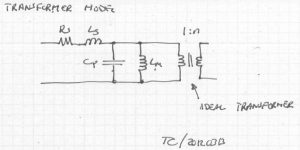
Any transformer can be modeled as shown in attached image. All components have been transformed to the primary. From a modeling perspective, it doesn't really matter if the parasitics are on the primary or secondary side, and when measured, they're all lumped together on the primary anyway.
Rs is the DC resistance of the windings.
Ls is the leakage inductance - basically, the inductance of the primary, secondary windings had the core been an air core.
Lm is the magnetizing inductance
Cp is the inter-winding parasitic cap.
The transformer on the right of the model is an ideal transformer. I.e. K = 1.0 and 1:n turns ratio.
n can be measured by counting the turns (if you're building your own tranny) or by applying an AC voltage to the primary and measuring the secondary voltage (CAREFUL!!). The turns ratio, n, is then Vsecondary/Vprimary.
Measure the impedance of the primary circuit with the secondary shorted. This yields Rs and Ls (Cp, Lm are shorted out by the ideal transformer and the short on the secondary).
Measure the impedance of the primary circuit with the secondary open (or loaded by a very high impedance - 10 MOhm for example). This gives you Cp and Lm (in series with Rs, Ls but as Z(Lm) >> Z(Ls+Rs) you mostly measure Lm||Cp).
On the 4194A, I use the Equivalent Circuits function (MORE MENUS -> EQV CKT). Circuit B ((Ls+Rs)||Cp) seems to work pretty well for these measurements.
~Tom
Attachments
- Status
- This old topic is closed. If you want to reopen this topic, contact a moderator using the "Report Post" button.
- Home
- Amplifiers
- Tubes / Valves
- Frequency Response of Output Tubes