Hi Tube Guys !
... obviously I am not much into tubes, but I always wanted to start playing with glass.
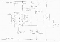
By chance I would need a gain stage + Buffer with high input impedance and the possibility to have inverting/non inverting inputs.
This seems to be a good starting point for me, because tubes offer high input impedance and reasonably nice noise figures at the same time.
Played around with simulations and this circuit seems to be promising...
Feel free to jump in and rip it apart
... obviously I am not much into tubes, but I always wanted to start playing with glass.
By chance I would need a gain stage + Buffer with high input impedance and the possibility to have inverting/non inverting inputs.
This seems to be a good starting point for me, because tubes offer high input impedance and reasonably nice noise figures at the same time.
Played around with simulations and this circuit seems to be promising...
Feel free to jump in and rip it apart
Attachments
Yes the anode resistors are low.
I have to run from low rails and still want to allow output levels up to +/-40V.
Furtheron the drive impedance for the BJTs appeared fine to me.
Last but not least, I want to keep it simple.
Of course this is not a natural match to most triodes, agreed.
But the 6DJ8 seemed to be a reasonable fit.
Which gain do you mean by 'OK gain'?
Open loop, Anode sloping divided by input sloping?
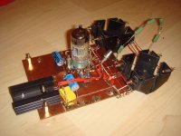
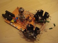
Here two pics from the proto.
Unfortunately I do not have ECC88 or 6DJ8 on hand.
For today I decided to play with an old ECC82 that I found in my playground.
From data sheets ECC82 is not reasonable here, but I simply could not wait until the 6DJ8 will arrive...
I have to run from low rails and still want to allow output levels up to +/-40V.
Furtheron the drive impedance for the BJTs appeared fine to me.
Last but not least, I want to keep it simple.
Of course this is not a natural match to most triodes, agreed.
But the 6DJ8 seemed to be a reasonable fit.
Which gain do you mean by 'OK gain'?
Open loop, Anode sloping divided by input sloping?
Here two pics from the proto.
Unfortunately I do not have ECC88 or 6DJ8 on hand.
For today I decided to play with an old ECC82 that I found in my playground.
From data sheets ECC82 is not reasonable here, but I simply could not wait until the 6DJ8 will arrive...
Attachments
Designed for maximum 'tube sound' i.e. lots of low order distortion?
In simulation the spectrum appeared to be reasonable.
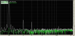
In reality with the preliminary set up with the ECC82 the distortions are not bad.
Funny thing is that that at +/-55V K2 does almost vanish, while at +/-50V and +/-60V it shows similar or even higher levels as K3.
Here the measurements with an output swing of 5Vp.
Attachments
Hm... at +/-55V not just K2 does vanish, but also K3 is pretty low.
In fact with that operating point on the ECC82 I am already in the range of positive Vg.
At Vg around 700mV there seems to be a minimum in distortion.
I think there was an old IEC paper on that..., but also read somewhere here in forum that such operating point would lead to unpleasant higher order distortion.
So far my measurement does not show this effect.
The triodes will create distortion with such low anode loads, but the NFB will reduce it again. Triodes are only linear with a high impedance load.
You might have problems with the output voltage bottoming on either the BJT collector or the CCS. This is because you have, in effect, two CCS both trying to control the same current. The BJT current is set by some resistors and the LTP tail CCS. Might not show up in simulation, where everything is perfect.
You might have problems with the output voltage bottoming on either the BJT collector or the CCS. This is because you have, in effect, two CCS both trying to control the same current. The BJT current is set by some resistors and the LTP tail CCS. Might not show up in simulation, where everything is perfect.
Which gain do you mean by 'OK gain'?
Open loop, Anode sloping divided by input sloping?
Sorry, typo - I meant OL gain...
Hi DF!
...., you mean I should spend the efforts to run from higher rails and put current sources to the anodes?
So far the circuit does not show any fundamental issues, the two CC tails do not fight each other. Please note all shown measurements in this thread are from the real proto, including distortion measurements.
Furtheron with the ECC82 there is not much loop gain to reduce distortions by feedback.
Hi SY!
Pentodes. Erhm, ... you know... I did not dare to start my glass excursion with pentodes.
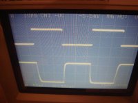
...and here a measurement on the step response, showing a +/-6V rectangle with 20kHz. (Probes: 10X).
...., you mean I should spend the efforts to run from higher rails and put current sources to the anodes?
So far the circuit does not show any fundamental issues, the two CC tails do not fight each other. Please note all shown measurements in this thread are from the real proto, including distortion measurements.
Furtheron with the ECC82 there is not much loop gain to reduce distortions by feedback.
Hi SY!
Pentodes. Erhm, ... you know... I did not dare to start my glass excursion with pentodes.
...and here a measurement on the step response, showing a +/-6V rectangle with 20kHz. (Probes: 10X).
Attachments
Great... in the mean time I fried by a short my 5V low noise reference of the current sources.
5V low noise reference is sounding great - say three red LEDs.
And the were not capable to handle the situation when connected between GND and -60V.
Ok, repaired. And I was already afraid if I would be possible to reproduce previous results. It was possible, now the lowest distortion is found at +/-53V.
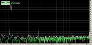
For reference now comparative distortion measurements in closed loop and open loop.
Open loop means putting the 8k2 from VAS output to GND in order to
have the VAS always operating into aproximately 8k2.
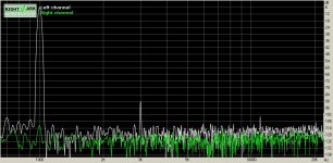
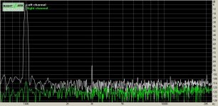
First graph is closed loop, second is open loop.
Input voltage was adjusted for both situation to achieve an output voltage of 5Vp. The 6db of global feedback in closed loop appear to be of minor importance for distortion.
5V low noise reference is sounding great - say three red LEDs.
And the were not capable to handle the situation when connected between GND and -60V.
Ok, repaired. And I was already afraid if I would be possible to reproduce previous results. It was possible, now the lowest distortion is found at +/-53V.
For reference now comparative distortion measurements in closed loop and open loop.
Open loop means putting the 8k2 from VAS output to GND in order to
have the VAS always operating into aproximately 8k2.
First graph is closed loop, second is open loop.
Input voltage was adjusted for both situation to achieve an output voltage of 5Vp. The 6db of global feedback in closed loop appear to be of minor importance for distortion.

I assume the 8k2 resistors are taking up the slack. As well as doing feedback they also provide the main BJT collector load.the two CC tails do not fight each other.
A null in second-order distortion could mean that grid current is cancelling gm curvature, but this is not a good thing as grid current probably won't be anything like a nice smooth second-order curve.
Without any load the VAS would have a huge DC gain, but lowish bandwidth.
And of course yes, with such high DC gain it would be hard to bias it in a way that wouldn't end up at one or the other rail.
I also dislike this adjustment which cancels the K2, because it is really just a very narrow spot of supply voltage range that fits. Already 1V more or less and K2 jumps up by 30db-40db.
I am curious for the 6DJ8. From data sheet, the operating point should be more reasonable - of course still facing the downside that the anode is operating from a low impedance.
Member
Joined 2009
Paid Member
I like it, real DIY.
I never use solid state CCS's, so if I were doing this I'd replace each one with a pair of resistors. For the LTP input I'd run a cap from the junction of these two resistors to ground for better PSRR. For each of the two transistors, I'd run a cap from the junction for the two resistors to the output to create bootstraps.
I never use solid state CCS's, so if I were doing this I'd replace each one with a pair of resistors. For the LTP input I'd run a cap from the junction of these two resistors to ground for better PSRR. For each of the two transistors, I'd run a cap from the junction for the two resistors to the output to create bootstraps.
If you have positive Vg (or grid current even with some negative Vg) then that means that you are trying to push too much anode current for the available anode voltage.
This and the low transconductance of the ECC82 are the reasons why I think that the ECC82 is not a good choice for this application.
Funny thing is that the anode characteristic of the ECC82 becomes mostly a straight line at a positive Vg around 0.7V.....
From traditional way of chosing operating points something like ECC88/6DJ8/6922 should fit much better. Don't you think so?
@Bigun:
... I am not sure if am getting all your proposals right.
Can you put it into a schematic?
Hi Tube Guys !
... obviously I am not much into tubes, but I always wanted to start playing with glass.
By chance I would need a gain stage + Buffer with high input impedance and the possibility to have inverting/non inverting inputs.
This seems to be a good starting point for me, because tubes offer high input impedance and reasonably nice noise figures at the same time.
Played around with simulations and this circuit seems to be promising...
Feel free to jump in and rip it apart
It is begging for bridged output...
- Status
- This old topic is closed. If you want to reopen this topic, contact a moderator using the "Report Post" button.
- Home
- Amplifiers
- Tubes / Valves
- DC coupled Sand 'n Glass with Current Feedback