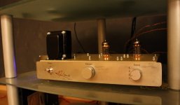
My narcissism makes me want to share this. A few hours ago, I finally brought to the world another healthy tube preamplifier. This one already has an almost identical older brother, so I'll give this one to adoption.
The newborn has two 12BH7 or ECC99 tubes and a healthy bandwidth up to 450kHz (-3dB), four inputs and an Alps volume pot. Output coupling capacitors are Obbligato Premium types.
Just some tube-a-rotica for your weekend...
The newborn has two 12BH7 or ECC99 tubes and a healthy bandwidth up to 450kHz (-3dB), four inputs and an Alps volume pot. Output coupling capacitors are Obbligato Premium types.
Just some tube-a-rotica for your weekend...
Attachments
Very helpful for those who wish to listen directly to longwave broadcasts on their supertweeters.
Yep, I know the BW is a bit over the top. 150kHz squares come out just nice at 20Vpp. Still, I just don't see any reason to limit it. Doesn't sound overly bright at all.
I use the same type of decal film that comes with model aircraft kits etc. I just print it out with a laser printer, cut them out, dissolve the base out in water, then transfer on the aluminum front plate. After they're dried, I apply several thin coats of lacquer. Between 5 and 7 coats is usually enough to make the edges of the films disappear. It's not silkscreening, and works only on light backgrounds, but given that you need no special tools besides a good knife for the cutting of the markings from the sheet, it gives quite nice results.How are you doing the front panel graphics?
Got a schematic you can post
Maybe I could... Basically it's just a CCS loaded ECC99/12BH7 common cathode directly coupled to a CCS loaded cathode follower, which uses the second half of the tube. I applied the basic topology by another finnish designer. It was originally using ECC82's, and was point to point wired, had a tube rectifier, and a lot less idle current. It also had both channels passing through the same tube, with the idea you could use a different tube for the different stages, giving you a possibility of varying the sound using for example an E80CC in the first stage and so on. I opted for a possibly better channel separation in my PCB version of the thing. The PSU is also slightly different, with SS rectification and more capacitance. Sounds and measures better than the original.
I'll try to remember posting the schema when I get home from work.
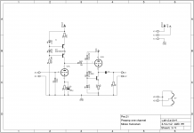
Here's the schematic for one channel. Pretty simple.
Hey, that's nice! Looks like something I'd do! (except I'd drop the cathode bypass capacitor in the first stage)
Do you have a drawing of your power supply and the voltages needed for the preamp stage?
At work again, I'll try to get to it later. SS rectification, CLCRCRC filtering. 280V for the input stage and 320 for the CF.
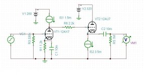
I tried the circuit first without the cathode decoupling, but had some hum problems. Works better this way. The CF CCS could be better, now that I think of it. At least the circuit seems to be reliable, the first one I made identical to this has worked without problems for three years now, and is in constant use. And the sound isn't bad either! At least one person preferred it over his Quad QC24 and Audio Research preamps, but this of course is subjective and a matter of taste. I measured a distortion figure of 0.19% at 2Vrms in (the volume pot is in the output side), but that includes the distortion of the generator I was using. I did'nt know it then, but only later measured that the 2nd harmonic of the Rigol generator was at -50dB...
I'm showing some 39dB of gain with 0.001% distortion @ 3volts output, 1kHz input. The current sources in the simulation have an internal impedance of 1M ohm. I tried it with your CCS arrangement and I think there's a problem with them. On the CF, I didn't have any bias. What bias do you measure on your CF and on the first stage? In the simulation, bias on the first tube is 1.8V, on the second it's about 1V. Obviously, the circuit inverts the signal phase also.
Attachments
Last edited:
I'm showing some 39dB of gain with 0.001% distortion @ 3volts output, 1kHz input. The current sources in the simulation have an internal impedance of 1M ohm. I tried it with your CCS arrangement and I think there's a problem with them. On the CF, I didn't have any bias. What bias do you measure on your CF and on the first stage? In the simulation, bias on the first tube is 1.8V, on the second it's about 1V. Obviously, the circuit inverts the signal phase also.
That sounds very, very wrong. But in your schema it shows an AX7 on the input? Wrong tube. The DC connected, CCS loaded CF biases itsself. It's cathode sits a couple of volts higher than the anode of the first stage, governed by the current set by the CCS. The first stage is biased at around 6V (1k2 * 5mA=6V)at the cathode. Both stages have ~5mA Iq.
That's better. Much closer to what I actually measured, aside from the distortion. I measured a gain of ~25dB with the ECC99 in place. It has a slightly higher mu than the 12AU7/ECC82.
I don't know if you asking for advice on this circuit, so I hesitate to make suggestions. It's already built anyway so there's no going back now. It's really nice looking. Glad you enjoy it.
I don't know if you asking for advice on this circuit, so I hesitate to make suggestions. It's already built anyway so there's no going back now. It's really nice looking. Glad you enjoy it.
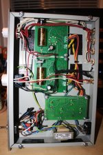
Built and the circuitry is on PCB's, so little room for modifications. As I stated earlier the first one of these has already served for three years or so, but now that I built another one, I see room for improvement. Doesn't matter really, though, since this is what I've been asked to do. Maybe a retrofit MKII PCB kit in the future... This one is part of a set of a preamp and two KT88 monoblocks I've been building for a friend; copies of what I already had.
I agree with dirkwright, that you should be able to eliminate C2 without significant performance degradation. Whether doing so subjectively improves the sound or not, only empirical evaluation would reveal. Assuming that the 'hum' you heard is not due to field coupling, I can only imagine that it is due to power supply coupling via the CCS. Short of reducing the ripple on the HV supply rail itself, you could improve the CCS by replacing that 100k bias resistor with a JFET or, better yet, a cascoded JFET. Perhaps, that might reduce the hum to in audible levels without dramatically redesigning the HV supply. Even though your CCS is cascoded, the biasing scheme is likely limiting the maximum impedance it might otherwise deliver.
Last edited:
What J-FET would take the voltage at that point? Good idea though, hadn't thought about CCS'ing the CCS references... But I don't think the hum is from the PSU. It's been so long since I debugged this circuit, but the PCB's in the first version didn't have the decoupling caps since I thought as well that they were unnecessary, but apparently the heater couples to the cathode capacitively or otherwise. Anyhow having that cap on the cathode made the hum lessen. I might try taking it out again, but having already soldered the boards in, I'm not enthusiastic about going back to do that. Currently I have zero problems with hum, the amp is sufficiently quiet.
If I redesigned the circuit now, I'd concentrate on improving the CF's CCS, not the first stage. It could have a higher dynamic impedance. It works OK, but could be better. Then again I just had the idea of applying my DAC output stage as a preamp, so I'm not likely to revisit this schematic anytime soon, since I'm already quite happy with it, and so is the "customer" who'll be getting the one on the opening post's picture soon. He's been waiting for a while already...
If I redesigned the circuit now, I'd concentrate on improving the CF's CCS, not the first stage. It could have a higher dynamic impedance. It works OK, but could be better. Then again I just had the idea of applying my DAC output stage as a preamp, so I'm not likely to revisit this schematic anytime soon, since I'm already quite happy with it, and so is the "customer" who'll be getting the one on the opening post's picture soon. He's been waiting for a while already...
I suggest either a JFET cascoded by a depletion MOSFET, or a depletion MOSFET cascoded by another depletion MOSFET - using a high-voltage depletion mode MOSFET as the cascode device is the main constraint. Below, is a link to some such devices from Supertex, there are others, such as from IXYS. As you said, perhaps, for a future project.
http://www.supertex.com/pdf/misc/d_mode_mosfets_SG_device.pdf
http://www.supertex.com/pdf/misc/d_mode_mosfets_SG_device.pdf
- Status
- This old topic is closed. If you want to reopen this topic, contact a moderator using the "Report Post" button.
- Home
- Amplifiers
- Tubes / Valves
- Joy of birth - a new preamp brought to the world