If you are going to try other tubes in the input check out 6n30p. 6n30p excels at low currents:
http://klausmobile.narod.ru/testerfiles/6n30p.htm
You mean low voltage. Yes, it can be used at 40-50v, but it still needs *at least* 8 mA through it to be linear!
You mean low voltage. Yes, it can be used at 40-50v, but it still needs *at least* 8 mA through it to be linear!
Yes, my bad. Thanks.
DF96, I beg you pardon. Yesterday I finished my DAC and put the 6N6P to work at 2,5mA current. It sounded well, dark. Today I tried running the 6N6Ps at 9mA - much better to my ears, I even want to increase the current more to try it. The instruments are more defined and the warm sounding of 6N6P is still here. The more I listen to music in this mode, I ask myself how could I have been listening to the previous ****.
Look at the transfer characteristics (Ug-Ia) graph in the datasheet. At 3-4mA you are operating the 6N6P in its most non-linear part... It needs at least 8-10mA to sound good!
Told you so.
.50 Action Express, right?
I like listening to music I'm not good at doing math but if I have to ask for technical advices I pick the guy with the math skill.
If I have to pick a builder to build my new house I pick the guy with the math skill and with well layout and measurement.
If you come up to me and say, I'll build your house and it'll look good and will last for ever but you can't show me a blueprint or any measurement, I'll pass.
Trust your senses is one thing but making argument with your senses is another, especially when it come to audio electronics.
Ears engineer vs real engineer, I know who I listen to for advice.
Just my 2cent.
Bad example, you would rather pick up an 80's Yamaha amp (very good measurements & 2D glass-like sound, barely listenable) and leave the much more worse measuring 300B SET amp (glorious musical & endless listening sessions) on the shelf!
Well, I understand what you are trying to tell. Even an 300B amp needs engineering and measurements to put out the full potential.
Regards
Good choice staying away from any Lampizator design.
The 6n6p seems quite happy at higher plate currents. Voltage suitable for what you want to run the tube at dissipation-wise. I usually aim for something over 20mA per triode. This is also where the plate resistance is at its lowest, which I think has great benefit in my transformer coupled designs.
I have also used the 6n6p at 6 mA per section in an LTP toplogy with good results. But this was driving EL34 outputs, not a preamp output. Best off with the higher currents imo.
I use them at 18-20mA as well and that's how I like them better!
But I use a bit more voltage
Hi
I'm using (one triode of) a 6N6P as the driver, via a 1:1 bifilar wound Border Patrol interstage transformer, in my 300B SE amp. 200V on the plate, 16 mA current, 7.7 V bias, grid stopper (1k I think, carbon comp). I chose these conditions as 16 mA suits the ITX well, and the operating point is well clear of the curved part of the characteristics; it's well within the plate dissipation limit; crucially, I can provide the bias using a MPSA92 as an emitter follower in the cathode circuit (emitter to cathode, collector to ground), with the base fed from a low noise LM329 6.9 V precision voltage reference; and, most importantly, it sounds superb!
The bias arrangement is Rod Coleman’s idea and works brilliantly. Low noise, very low dynamic impedance, and rock solid fixed bias. The sonic improvement over other bias arrangements was marked! I feed the LM329 ~2 mA from the HT supply to the stage (~230V), tapped via a 47k series resistor/22u Pan NHG to ground - 47k series resistor. I protected the reference from overvoltage at switch on by putting a 12 V zener across it.
From visual inspection of the datasheet, I estimate, under these conditions, that mu is only 13-14, S about 7 mA/V, and rp 1k9. So mu is considerably lower than you might expect from a casual inspection of the data (I must measure it in practice). So max output swing is probably only ~ +/- 105 V, not the > +/- 150 V I had hoped for (twice that required for full output, but this seems best practice to minimise distortion in ITX-based drivers). Good thing my preamp has a gain of x 30- it uses a E80CC with cascoded FET CCS load (available as the “caresser” pcb from Paul Hynes). Output is taken from the source follower element of the CCS circuit
Paul N
@spswmsw: 400-450 volts? Jesus, is that not a bit too much for the 6N6P? I'm driving it with 120v/Rcat:120R/Ra:15k approx. 18mA.
YEP, plate voltage should be 120 to 160V.
I use 150V (plate voltage), but total psu voltage 300V
Ea is NOT Ua
Ea is a power supply voltage
Ua is a plate voltage
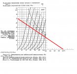
Under 420 V power supply and 12 k anode load the plate dissipation is less than maximum threshold for this tube (dashed curve).
Just such a mode is preferable to drive 'heavy" output triodes (no impact of their input impedance due to Miller’s capacity ).
Taking into account the outstanding linearity of 6N6P one can chose the bias point here in a rather wide range.
Sincerely yours.
Ea is a power supply voltage
Ua is a plate voltage
Under 420 V power supply and 12 k anode load the plate dissipation is less than maximum threshold for this tube (dashed curve).
Just such a mode is preferable to drive 'heavy" output triodes (no impact of their input impedance due to Miller’s capacity ).
Taking into account the outstanding linearity of 6N6P one can chose the bias point here in a rather wide range.
Sincerely yours.
Attachments
Last edited:
Ea is NOT Ua
Ea is a power supply voltage
Ua is a plate voltage
Under 420 V power supply and 12 k anode load the plate dissipation is less than maximum threshold for this tube (dashed curve).
Just such a mode is preferable to drive 'heavy" output triodes (no impact of their input impedance due to Miller’s capacity ).
Taking into account the outstanding linearity of 6N6P one can chose the bias point here in a rather wide range.
Sincerely yours.
Yes, something like 140V plate voltage and 23mA plate current?
I use a bit lower value for plate load, but not that far.
Yes. You're right.Yes, something like 140V plate voltage and 23mA plate current?
P.S. I have a colleague who uses 540 Volts psu and 8k2 anode loads. As for me it is some kind of "marginal" experience. Sound is then a bit specific ("coarse").
Last edited:
Anyway, I think the 6N6P when correctly used is one of my favourites, and will put most other to shame (6H30 included)
I almost agree and support Your opinion.
As for me only ECC81 can be compared here.
I've seen that before, and the sound quality does not only depend on how much, but mostly on what kind of distortion.
anyway I'd bet if he pushed the tube towards 20mA the results would have been different.
Anyway, I think the 6N6P when correctly used is one of my favourites, and will put most other to shame (6H30 included)
Psssst, don't tell anybody - let the fools run their ugly & mechanical sounding ECC81's, 6DJ8's and other nasty tubes....
")
- Status
- This old topic is closed. If you want to reopen this topic, contact a moderator using the "Report Post" button.
- Home
- Amplifiers
- Tubes / Valves
- 6N6P best musicality? Help with modes.