So, back in the 1930's, researchers had a problem. They wanted to measure skin voltages on humans but because of the very large hum fields and the very small voltages involved, ordinary amplifiers could not work. So, through experimentation they devised the differential amplifier and invented common mode feedback.
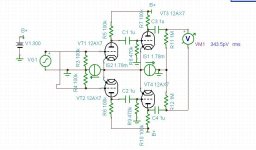
I thought I'd play around with this idea using tubes, pretending I was back in the 1930's and trying to measure microvolts in a high voltage environment. This circuit has a gigantic common mode rejection ratio, as well as high gain of almost 70dB and distortion of less than 0.003%. The common mode rejection is so high I'm not sure it's correct in my calculations. With a common mode input of some 7 volts rms, output voltage is 340pico volts rms (340X10^-12). I think that's 200dB, but I'm probably wrong.
The 100% common mode feedback is the wire between the joined cathodes of the two differential amplifiers. This would be a great gain stage for something like a moving coil phono cartridge, if the noise isn't a problem. The CCS are set for an internal impedance of 1M ohm. Disconnecting the common mode feedback increases the distortion by about 10 times. Bandwidth is not great, with the -3dB point at about 50kHz. Different tubes may give different results.
In the attached figure, the voltage generator source is wired up for common mode input. The output can be seen as 343pV rms.
Anyway, just thought I'd share.
Attachments
Neat... I haven't mucked with common mode feedback with tubes myself, but in the semiconductor world, CM feedback is a known source of trouble. CM feedback loops are notorious for being unstable - or difficult to make stable. Just sayin... Beware.
Nice circuit, though.
~Tom
Nice circuit, though.
~Tom
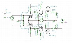
So, I added a couple of followers so this little preamp can actually drive something. With 0.7mV rms input, output is over 2 volts rms with distortion @ 20kHz of about 0.002%. I think that's pretty good for no global feedback. Bandwidth is still pretty good with 70dB of gain and -3dB @ about 40kHz. I changed the CCS a little also.
This is an ideal situation with matched tubes and parts. Real world performance would be less of course.
Someone could put a balanced passive RIAA filter between the second gain stage and the follower stage for a pretty nice phono preamp. I would hook up the phono cartridge in a balanced line arrangement instead of the usual single ended one. I wrote an article about that 20 years ago. You just take the + and - from the cartridge for each channel separately and floating from ground. Simple.
Attachments
Last edited:
You did make sure that each triode has different characteristics, didn't you? Otherwise all you are seeing may be floating point rounding errors.
No, this is idealized fantasy world simulation. I haven't built any tube gear in almost 20 years. I'm just enjoying "fantasy high fidelity", where I pretend I have the ideal system and I can actually hear out to 20kHz.
Neat... I haven't mucked with common mode feedback with tubes myself, but in the semiconductor world, CM feedback is a known source of trouble. CM feedback loops are notorious for being unstable - or difficult to make stable. Just sayin... Beware.
Nice circuit, though.
~Tom
Thanks! I'm impressed that the distortion is so low without global feedback.
Very interesting circuit, but 200 dB seems too much.
Thanks sharing these stuff.
Yeah, it's all about ideal parts and such. I doubt a real world circuit would perform this well, but it's nice to imagine it would do that.
Are the simulator tube models simple 3/2 power triodes? Very interesting that it reduces distortion. I would guess that the 2nd stage normally has more tail voltage variation with it's bigger signal, so that variation is increasing the tail V variation for the 1st stage here too.
edit:
What happens if you move the CCS over all the way to the right now so that all three stages share the same tail? Or would that cause common mode positive feedback?
edit:
What happens if you move the CCS over all the way to the right now so that all three stages share the same tail? Or would that cause common mode positive feedback?
Last edited:
The first two stages have heavy feedback, and the CF has heavy local feedback. Hence low distortion.I'm impressed that the distortion is so low without global feedback.
The first two stages have heavy feedback, and the CF has heavy local feedback. Hence low distortion.
The first two stages have 100% common mode feedback only. Like any differential amplifier though, there is feedback through the common tail load. Maybe that's what you mean.
Are the simulator tube models simple 3/2 power triodes? Very interesting that it reduces distortion. I would guess that the 2nd stage normally has more tail voltage variation with it's bigger signal, so that variation is increasing the tail V variation for the 1st stage here too.
edit:
What happens if you move the CCS over all the way to the right now so that all three stages share the same tail? Or would that cause common mode positive feedback?
I got the spice models for the tubes off of the web somewhere:
* 12AX7A Triode PSpice Model 8/96, Rev. 1.0 (fp)
*
* -------------------------------------------------------------------
* This model is provided "as is", with no warranty of any kind,
* either expressed or implied, about the suitability or fitness
* of this model for any particular purpose. Use of this model
* shall be entirely at the user's own risk.
*
* For a discussion about vacuum tube modeling please refer to:
* W. Marshall Leach, jr: "SPICE Models for Vacuum-Tube Amplifiers";
* J. Audio Eng. Soc., Vol 43, No 3, March 1995.
* -------------------------------------------------------------------
*
* This model is valid for the following tubes:
* 12AX7A/ECC83, 7025, 6EU7, 6681, 6AV6, 12DW7/7247 (Unit #1);
* at the following conditions:
* Plate voltage : 25..400V
* Grid voltage : 0..-3.5V
* Cathode current: 0..8mA
*
*
* Connections: Plate
* | Grid
* | | Cathode
* | | |
.SUBCKT 12AX7A P G K
E1 2 0 VALUE={45+V(P,K)+95.43*V(G,K)}
R1 2 0 1.0K
Gp P K VALUE={1.147E-6*(PWR(V(2),1.5)+PWRS(V(2),1.5))/2}
Cgk G K 1.6P
Cgp G P 1.7P
Cpk P K 0.46P
.ENDS 12AX7A
With an ideal triode low distortion is likely. Your model appears to have constant mu. A real ECC83 would be good too, but not that good.
I probably was getting confused by the common mode feedback.
Yeah, I dunno. I'm just fooling around. This is "fantasy vacuum tubes" for me...

My story about how common mode feedback was invented is true though. I used to have a copy of the article from the 1930's.
"Gp P K VALUE={1.147E-6*(PWR(V(2),1.5)+PWRS(V(2),1.5))/2}"
Yep, 3/2 power modeling. (the 1.5 powers, not sure why its got PWR and PWRS though, seems to be averaging them) With constant Mu (the 95.43 above).
Might be interesting to vary the Z of the CCS to see if the distortion is maximized at some specific Z or just at the inf. Z.
I wonder if this common mode feedback scheme would lower distortion for a diffl. driver and output stage combo.
The usual scheme for minimising 3rd harmonic is to use a specific Z in the tail of a diffl. pair. But this common mode fdbk scheme seems to be doing the opposite. Maybe the 2nd stage is doing the distortion comp. by being dragged by the 1st stage? Would be interesting to put a pure sine wave in and observe the 3rd harmonic at the output of the 1st diffl. stage and at output of the 2nd diffl stage to see if the 3rd H distortion % first goes up then back down to cancel. This could be very significant if it can be used to cancel odd H distortions.
Last edited:
Yeah, I thought I had invented the Elliptron and the vacuum tube current mirror too until I found them in old references. Maybe this is why some cultures burn libraries occasionally. They get to re-invent things.
(now if I could just round up every last copy of those old used books.......)
(now if I could just round up every last copy of those old used books.......)
Last edited:
I guess one could look at the common tailed common mode feedback scheme above as the combination of two SE double stages with conventional cathode to cathode (neg. fdbk ? wait, its positive fdbk!) feedback. Just gets constrained in P-P mode to correcting only the odd harmonics (and the common mode signal too).
Last edited:
I guess one could look at the common tailed common mode feedback scheme above as the combination of two SE double stages with conventional cathode to cathode feedback. Just gets constrained in P-P mode to correcting only the odd harmonics.
Or, you can look at it as a differential pair of asymmetric multivibrators.
Positive and negative feedbacks compensate each other if tubes and resistors are identical.
Last edited:
- Status
- This old topic is closed. If you want to reopen this topic, contact a moderator using the "Report Post" button.
- Home
- Amplifiers
- Tubes / Valves
- Common mode feedback