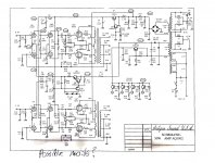
I have problem with my old ASL AQ1002 amp which I can't solve. Can somebody explain me which parts are responsible for input tubes VB1 ,Vb2 plate voltages of 163V like in schematic attached? All of the rest voltages are close enough with 325 V after regulator and around 270V to R3, R4 ;R28, R29 but plate voltage stays at 80V instead 163. I can set the bias properly to -115 and the second stage VB2 , VB6 operates more or less properly. My friend simmed the input stage at one point and he said the schematic is correct and there should be this damn 160V on . TIA, L
Attachments
Hi,
I would check the negative supply of -115V supplying the cathodes of the input LTP Phase-Inverter VB1. (Too bad they didn't take the opportunity of doing a CCS Constant-Current-Source, when the negative supply is already present. Now it would be a good place to start modding the amp. if you're not afraid of sand ...well, there's already sand in this amp. )
Rgds,
/tri-comp
I would check the negative supply of -115V supplying the cathodes of the input LTP Phase-Inverter VB1. (Too bad they didn't take the opportunity of doing a CCS Constant-Current-Source, when the negative supply is already present. Now it would be a good place to start modding the amp. if you're not afraid of sand ...well, there's already sand in this amp.
)Rgds,
/tri-comp
R5, C14 (especially C14) and also the plate resistors should be checked. Looking at the circuit it is odd that they use a -115 supply, also check that, and only pull the tail to a POSITIVE voltage... hmmm... but it still needs to work properly. Seems like a waste of a 115volt negative supply to me... but who knows?
And of course if the tubes do not work the plate voltage will hang high because there is no current being drawn.
_-_-bear
EDIT: wait a sec, the voltage is low... still check if the resistors could be shifted in value. But look at the current through the tail resistor and the plate resistors (vdrop applied to ohms law) Sometimes resistors will show heating effects (look with a magnifying glass) and will test ok with an ohmeter but not work under load.
IF they are proper values then crank the -115 until the plate voltage runs back up, turn it and see what happens, you should be able to see the current reduce as the bias on the grid changes WRT the cathode voltage. If the voltage rises back up and all the passive parts are ok, then just leave this Vset where it wants to be for this set of tubes... at 80vdc on the plates you should see excess current draw, look at the tube manual to see where quiescent current wants to be for normal fixed bias operation and set it for that (approximately). Should be fine. I would expect.
Last edited:
The negative supply of -115 is there but I'm reading 3.4V of supposed 7.6v on trimpot VR1 side of R2 , R42 . I have no problem employing CCS , just first have to figure out whats wrong with it and where that voltage sinks .(also need to read a little more theory , it got rusted over the years
R5, C14 (especially C14) and also the plate resistors should be checked. Looking at the circuit it is odd that they use a -115 supply, also check that, and only pull the tail to a POSITIVE voltage... hmmm... but it still needs to work properly. Seems like a waste of a 115volt negative supply to me... but who knows?
And of course if the tubes do not work the plate voltage will hang high because there is no current being drawn.
_-_-bear
Thanks, there is no voltage drop after C14 , I mean it supplies ~270V instead 288V which is a ballpark . Only after R3, R4; R28 ,R29 plate resistors (or dividers ) instead of 163V I'm getting 80V
Each triode of 12au7 draws 1.5mA (I measured Vk across VR1 leg and middle of the pot) Both channels behaves the same. 120k anode resistors measure OK.
The scematic shows 7.6V on VR1 trimpot side of R2 (-115) but I'm getting just 2.3V . I can only adjust to -100 V
The scematic shows 7.6V on VR1 trimpot side of R2 (-115) but I'm getting just 2.3V . I can only adjust to -100 V
Last edited:
You're actually compromising driver stage headroom significantly by not addressing the issue.
The most effective way to fix this issue is to change the values of R2 and R42 - if I remember correctly you need to change these to about 68K. (My old PP designs are generally similar and have similar sensitivity to tail voltage) You can experiment with values in the range of 47K - 75K..
I used to have a mod for this model, but probably won't be able to locate it.
Kevin , Thanks! It is actually model 102 (older than 1002 but schematic mostly the same) with gold face plate. What was specific area of the mod? I was thinking of adding a little PSU capacitors in ARC style. (already changed those fake Elna Ceraphines to 2 xJJ 500uF) Amp doeasn't sound half bad actually . It's pretty clean and spacious with nice ballance , oh I substitued driver 12au7's with 6CG7's (filament swap).
OK, That was it . R2, R42 supposed to be 56K on schematic but they were both 38K in the amp. I added 33k and all is good. :0)
OK, That was it . R2, R42 supposed to be 56K on schematic but they were both 38K in the amp. I added 33k and all is good. :0)
Last edited:
The driver stage was a bit different, used a 5751 in the first stage and a 12BH7 in the second. No balance pot in the front end. The existing design implemented with the 6CG7 should be fine.
Differences between the 12AU7 and the 6CG7 may account for some of the problems you are having, they are just a little different in terms of transconductance for a given bias and plate voltage. Changing those two resistors should get you where you need to be I think. Set the balance pot so that the plate voltage on the second stage plates matches well for best overall symmetry. (Within a couple of volts is generally OK)
Differences between the 12AU7 and the 6CG7 may account for some of the problems you are having, they are just a little different in terms of transconductance for a given bias and plate voltage. Changing those two resistors should get you where you need to be I think. Set the balance pot so that the plate voltage on the second stage plates matches well for best overall symmetry. (Within a couple of volts is generally OK)
Ok , I changed them and all is fine , thanks a bunch!!!! The amp was blowing output tubes and melting PCB board (where screen cathode resistors were installed) when I've got it. Part of it was faulty tubes but I think octal sockets are culprit and needs to be cleaned frequently.
- Status
- This old topic is closed. If you want to reopen this topic, contact a moderator using the "Report Post" button.
- Home
- Amplifiers
- Tubes / Valves
- Stuck with repair ;(