Hi,
Here is the wire out for the isolation
transformers I have
http://www.antrimtransformers.com/colour_codes.htm
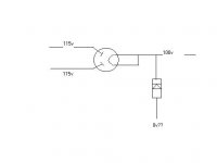
The transformer has twin 115v primaries, and I have wired them as follows
white and black together, pink to ac hot and brown to ac cold. which is fine for the european 230v.....
the output stage is here,
http://www.ultranalog.com/cdenhancer/cdenhancer2_3a5.pdf
If I link the yellow and blue secondries, they become the centre tap, but I think I would then get 230v accross the circuit??????
If I link the red and blue secondries and the grey and yellow I get 115v-115v, which is still unsuitable cause I have no centre tap????
I have three of these transformers which I got cheap, but are they unsuitable for the above circuit???
Thanks
Raja
Here is the wire out for the isolation
transformers I have
http://www.antrimtransformers.com/colour_codes.htm
The transformer has twin 115v primaries, and I have wired them as follows
white and black together, pink to ac hot and brown to ac cold. which is fine for the european 230v.....
the output stage is here,
http://www.ultranalog.com/cdenhancer/cdenhancer2_3a5.pdf
If I link the yellow and blue secondries, they become the centre tap, but I think I would then get 230v accross the circuit??????
If I link the red and blue secondries and the grey and yellow I get 115v-115v, which is still unsuitable cause I have no centre tap????
I have three of these transformers which I got cheap, but are they unsuitable for the above circuit???
Thanks
Raja
would this work???
Hi,
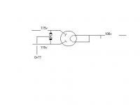
Okay if I have only 115v-155v secondries, I can see 2 options
1) Is to use 2 isolation transformers, with one wired directly to mains, providing 115v-155v on the secondries. The secondries would then be wired to the primaries of the second transformer, which sholud give me a 115v-0-115v secondries.
Or please correct me if I'm wrong!!!
to use a diode on the output of the rectifier like this;
Thanks
Raja
Hi,
Okay if I have only 115v-155v secondries, I can see 2 options
1) Is to use 2 isolation transformers, with one wired directly to mains, providing 115v-155v on the secondries. The secondries would then be wired to the primaries of the second transformer, which sholud give me a 115v-0-115v secondries.
Or please correct me if I'm wrong!!!
to use a diode on the output of the rectifier like this;
Thanks
Raja
Attachments
Hi,
In the hybrid rectifier as shown there is NO switching noise so a simple pair of 1N4007 would do just fine.
Cheers,")
It would reduce switching transcients and reduce noise presumably...
In the hybrid rectifier as shown there is NO switching noise so a simple pair of 1N4007 would do just fine.
Cheers,
Hi everyone,
The transformer I have is rated at 120va.
Another silly question for you all
in ultranalog's schematic, he's attatched pins 3 & 4 to B+.
But in the diagram shown in the az1 pinout data only pin 3 is connected to B+.
I've tried the rectifier like in the data sheet with only pin 3 connected accross 1 of the 47 ohm resistors, I'm getting 175 volts at this point.
So should pin 2 be connected also???
Or should I just be using pin 3, and the 47 ohm resistors in parrallel?
Thanks
Raja
Hi Fdegrove,
Should I connect like this,
http://www.diyaudio.com/forums/attachment.php?s=&postid=232367
only pin 3 to B+
or this?
http://www.ultranalog.com/cdenhancer/cdenhancer2_3a5.pdf
both pins 2 & 3 to B+
Sorry if I'm getting confused here, ultranalog's schematic just looks a bit different to the datasheet................
IN any case it looks as if I'm getting to much volatge on B+ it's reading 175 volts after the 680 ohm resistor.
The max for the 3a5's is 135 volts. How come it's so high?
I measured 130v accross the secondries with my dmm. Antrim does state that the reading will be higher than the stated 120v in off load conditions, but I figured it wouldn't be over by this much...
Luckily I havn't yet connected the 3a5's to the circuit.
The choke has a stated dc resitence of 150 ohms.
Can I drop the voltage to a safe margin with another resistor after the 680 ohm res?
Thanks
Raja
Hi,
I don't see that in the PDF file you link to but nevermind...
2 and 3 are connected to the heater supply and the output is behind the 2 resistors. That's your B+.
Either way will work but you'll probably have a little too much voltage.
Cheers,
both pins 2 & 3 to B+
I don't see that in the PDF file you link to but nevermind...
2 and 3 are connected to the heater supply and the output is behind the 2 resistors. That's your B+.
Either way will work but you'll probably have a little too much voltage.
Cheers,
Too much voltage
The az1's glowing nicely.........
Yep you're right, either way I get 170v after the 680ohm resistor at the end of the circuit.
I doubt whether the total of 14ma drawn by the 3a5's is going to cause 'major sag' on the rail.
1) How many volts can I expect the rail to drop once the 3a5's are connected?
2) So how can I work out how much more resistence I need to get the right voltage at the output?
3) Why has the voltage risen by so much, I thought tube rec's dropped around 15v, and yet here I am with more voltage at B+ than at the secondries....?
Thanks
Raja
dropping voltage
Hi,
Have I worked this out right???
R=V/I
R=110/0.014
R=7857 ohms
7K 857 ohms?????
So if I subtract from 7857, the total value of resistence in the circuit, I should get the value I of resistor I need to drop the voltage???
By the way using my dmm I checked the resistence on the choke pins, which read 270 ohms.
so 680+270+47= 997
7857-997= 6860
I do realise my questions must be irratating guys, but I'm learning, and I do apologise for taking up so much of everyone's time......
Thanks
Raja
Hi,
QQ 1 & 2 Ohms law allows for the calculation of that.
Don't work on circuits without a load attached, use a lightbulb or a 15W 470K resistor or similar.
Q 3 I did tell you to remember you're working with a full wave rectifier, hence the higher rectified B+.
Cheers,
Edit: Just noticed your latest post: yes, 7000 ohms = 7K.
Hi,
Don't forget the internal resistance of the 3A5s as well.
Easiest way to go about it is to build the circuit, check it for short, put the valves in place, than measure the B+ after a few minutes warm up.
See how much voltage you need to drop and using Ohms' magic adjust the dropping resistors.
Always check that the circuit is fully discharged befor putting a hand in it.
Cheers,
7857-997= 6860
Don't forget the internal resistance of the 3A5s as well.
Easiest way to go about it is to build the circuit, check it for short, put the valves in place, than measure the B+ after a few minutes warm up.
See how much voltage you need to drop and using Ohms' magic adjust the dropping resistors.
Always check that the circuit is fully discharged befor putting a hand in it.
Cheers,
- Status
- This old topic is closed. If you want to reopen this topic, contact a moderator using the "Report Post" button.
- Home
- Amplifiers
- Tubes / Valves
- is this transformer ok??