Folks,
I like to have the heatsinks in my project grounded for safety reasons. But I've noticed that when mounting a TO-220 like the IXYS 10M45 CCS to a grounded heat sink, I often get a high-voltage breakdown (sparks, carbonization, short circuit) between the tab of the device and the mounting screw. The breakdown seems to happen right where the shoulder washer ends on the back side of the TO-220.
I measure the resistance from the TO-220 tab to the heat sink with an ohmmeter before turning the power on. I have had cases that would short out even though the meter showed no connection from tab to heatsink.
Are some TO-220 mounting kits rated for higher voltages than others? How can I avoid this breakdown issue?
~Tom
Hi Tom,
What sort of voltages are we talking here? I've not had problems at 200V and below in recent times and built some Maidas back in the '80's that ran at much higher voltages (330V out and 350 - 360V in). I use nylon screws and silpads where the power to be dissipated is low since nylon is not particularly good for clamping.. I always drill the mounting holes in heat sinks roughly a drill size large than the fastener and debur carefully before installing the insulator. (I usually use mica/grease for higher dissipation and silpads with nylon or stainless steel screws for modest dissipations.)
In some instances I also use small ungrounded heat sinks on vector board inside a chassis where they cannot be touched in normal operation.
What sort of voltages are we talking here?
I've had issues from 150~200 V and up. In recent incarnations of my current amp design, I've run B+ of 400 and 470 V and experienced fireworks at both voltages.
I'm using the silicone pads as they're so much more convenient than the mica+goop. But I've also noticed that after they get covered in carbon from the breakdown arc, they don't insulate very well anymore...
")
I use nylon screws and silpads where the power to be dissipated is low since nylon is not particularly good for clamping..
Yeah... That's my concern as well. Nylon tends to stretch so you don't get good clamping pressure.
In some instances I also use small ungrounded heat sinks on vector board inside a chassis where they cannot be touched in normal operation.
That may be where I end up in the final design, but I'd still like to figure out a reliable way for isolating TO-220's when mounted on a grounded heat sink. That's handy for prototyping and such.
~Tom
What I use for high voltage TO-220 mounting:
Aavid 7721-8PPSG PPS material shoulder washer .040 x .245 oversized shoulder
Aavid 4170G Al oxide ceramic insulating pad
the ceramic pads are awesome, about .050 thick and reusable
All heat sink mounting is super sensitive to nice flat clean surfaces
PS I don't know if perhaps some of the heatsink compound (arctic silver, etc.) is electrically conductive but I stick to the white stuff.
Last edited:
The payback for the SILpad convenience is the high sensitivity to punctures. They're good for kV when everything is polished flat and cleaned down - but totally intolerant to one speck of swarf.
I've noticed that as well. Also, I've noticed that the hole for the screw is pretty large in the SILpads I have. I think it's made for a 4 mm (#6) screw. I use 3 mm screws...
I'm using a pretty small heat sink. They're made for TO-220 packages but have a slot where the screw goes rather than a hole. I'm wondering if the thermal pad ends up getting pinched on the slot edges. I'm using something else for the final product, but for prototyping these small heat sinks are pretty handy. Well, aside from the arcing that is...
~Tom
I have blasted through the sil pads too, but I was running about 500 volts on some big Fuji TO247 fets. Made a big bang and fried the plastic on the fet. The fet was still alive but wasn't flat anymore. The bang took out a 2 amp line fuse.
I got some new pads and will try coating them in white goo first. There is no plastic washer on a TO247. The hole is plastic and the metal contact area is spaced away from the hole. I might have torqued the screw a bit too much, so I will try a 6 inch pound calibrated screwdriver. This time there will be 4 fets per big heatsink with only 350 volts. This is for the mother of all driver boards for screen drive and other extreme tube amp experiments.
I got some new pads and will try coating them in white goo first. There is no plastic washer on a TO247. The hole is plastic and the metal contact area is spaced away from the hole. I might have torqued the screw a bit too much, so I will try a 6 inch pound calibrated screwdriver. This time there will be 4 fets per big heatsink with only 350 volts. This is for the mother of all driver boards for screen drive and other extreme tube amp experiments.
I have blasted through the sil pads too, but I was running about 500 volts on some big Fuji TO247 fets. Made a big bang and fried the plastic on the fet. The fet was still alive but wasn't flat anymore. The bang took out a 2 amp line fuse.
I got some new pads and will try coating them in white goo first. There is no plastic washer on a TO247. The hole is plastic and the metal contact area is spaced away from the hole. I might have torqued the screw a bit too much, so I will try a 6 inch pound calibrated screwdriver. This time there will be 4 fets per big heatsink with only 350 volts. This is for the mother of all driver boards for screen drive and other extreme tube amp experiments.
The ceramic pad for TO-247, TO-3P, etc is Aavid p/n 4180G
I was able to use these at ~500V swinging up to >800V with no problems
http://www.diyaudio.com/forums/tube...r-triode-strapped-pentode-12.html#post2207735
Last edited:
I gotta believe we're burning through those SILpads because the mating surfaces aren't completely clean. It wouldn't take much of a burr to create a connection through one of those pads. At least all of Aavid's products are rated at breakdown voltages in excess of 4 kV. Pretty impressive...
~Tom
~Tom
The ceramic pad for TO-247, TO-3P, etc is Aavid p/n 4180G
Digikey wants a minimum order of 6000 units, but Mouser has stock at 92 cents each. I will get some on my next order just in case I decide to turn up the volts. I am using the multi tapped Edcor "tinker box" power transformer with the output stacked on top of a 120 volt isolation transformer. I get output voltages from +/- 40 volts to +/- 550 volts.
I gotta believe we're burning through those SILpads because the mating surfaces aren't completely clean.
I know that the heat sink, pad and mosfet were wiped down with alcohol and were clean. The heat sink I used on the last experiment was tapped before it was anodized and burr free. It was brand new and still in the box. It wasn't big enough for my purpose and got quite warm. Thermal cycling probably weakened the pad in the area that failed. Overtorquing was probably a factor too.
I got bigger heat sinks, but I must drill and tap them myself this time. I will be careful to clean things up before another big bang. No torque specs in the Aavid lit though.
I know that the heat sink, pad and mosfet were wiped down with alcohol and were clean. The heat sink I used on the last experiment was tapped before it was anodized and burr free. It was brand new and still in the box. It wasn't big enough for my purpose and got quite warm. Thermal cycling probably weakened the pad in the area that failed. Overtorquing was probably a factor too.
Hmmm... Another thing is that those pads are really quite thin. 6 mil (0.15 mm). With the oversize hole in the SILpads for TO-220 packages, it may just be the air between the package and the heat sink that's breaking down. As I recall, air breaks down around 1 kV/mm. So 150 V should be enough to cause breakdown to occur on those SILpads.
~Tom
Only my opinion,
I think the pads are only any good at low voltage and I would give them a miss on anything above about 50V. I clamp with brass screws "wide head" and have been known to put two mica (white compound between) pads on anything above 500V if the current /heat is not at lava level. Plus I also only use the white compound.
One thing i notice is the insert on some pads rips easily I don't trust them.
I also use the package with insulated through hole..can't remember the package number off hand.
It has been suggested that a plate/strip should be used with multi transistors and clamp screws between the components on high voltage.
You know the pads are soft and flexible...What happens to a soft material under constant pressure? If it spreads then the component will become loose...or it will twist easily. If it gets thin due to pressure...I'll stick with mica and compound..the ceramic sounds interesting I have never tried it.
Regards
M. Gregg
What happens to a soft material under constant pressure?....If it gets thin due to pressure...
Constant pressure and cycled heat. The insulators on the fets that didn't fail didn't look right. The new parts have a textured look to them. The parts removed from the heat sink had lost that textured look in an area between the screw hole and the leads, in the center of the metal head spreader on the mosfet. This would imply that the clamping load was not equal across the entire surface.
Most of my PowerDrive experiments have used the all plastic TO220 mosfets without insulators, just the goo. This experiment will go beyond the SOA of those little devices, so I am going to use the TO247's. I think I will wait for the ceramic Aavid parts and see how they work.
Many, many moons ago, when I repaired TV's for a living, I had a Toshiba set in for repair, with a failed line output transistor. This transistor was a TO-218 package, with metal tab. It was pressed against a black anodised heatsink by a spring clip. It had lasted over 4 years WITHOUT an insulating mica washer! The anodising alone had insulated it! There are 1KV pulses on that tab... amazing! If anything approaches ~300V, I use either a spring clip, or the easier method of aluminium bar and a couple of M3 nuts and bolts either side of the transistor, clamping the plastic body of the transistor. Insulated with a nice mice washer without the hole.
I clamp with brass screws "wide head" and have been known to put two mica (white compound between) pads on anything above 500V if the current /heat is not at lava level. Plus I also only use the white compound.
"Heat at lava level"... Like it.
It sounds like the two mica pads give you enough separation to avoid trouble with arcing in the air gap between the heat sink and the package.
Sounds like that's the main advantage of the ceramic or alumina/aluminum oxide isolators as well.
One thing i notice is the insert on some pads rips easily I don't trust them.
Yeah... That's been my experience as well.
I also use the package with insulated through hole..can't remember the package number off hand.
Sounds like a TO-247. That's a rather large package. 5-ish mm pin spacing. Used on high wattage MOSFETs and such.
I'm having good luck with the TO-247's I use in my high voltage regulator. Even with the SILpads, I'm not getting any arcing. I'd probably change to goop + alumina or mica instead, though.
You know the pads are soft and flexible...What happens to a soft material under constant pressure? If it spreads then the component will become loose...or it will twist easily. If it gets thin due to pressure...
My experience with the high voltage regulator - which tends to run with a 50-ish deg C heat sink temperature in my setup - has been that the SILpad gets squished and forms to fill the gaps between the transistor case and the heat sink. I usually have to tap the device pretty hard with a screwdriver to get it off. So I think it does the job just fine on a TO-247 package.
But with the TO-220 and the over-sized holes in the SILpads I'm using, I don't think I'm getting good enough isolation due to the design of the SILpad. I'm sure I'm not the first to discover this.... After all, it didn't take long after switchmode supplies using high voltage FETs became mainstream for the TO-220IS isolated package to be developed.
~Tom
I remember before Bob Widlar's days when the TO220 package came out, I never liked it as this package is sensitive to improper mounting and will pincushion soft silicone pads and needs a hard surface.
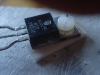
I'm surprised some of you don't like the idea of nylon screws or equiv material as shown in pic, for years I regulary use polyamid screws throughout my projects with ceramic washers. Never had an issue with them and their elasticity is a bonus. The trick is to avoid overtightening and also stressing the device with poor pcb mounting and making sure it is dead flat.
richy
Attachments
Sounds like a TO-247. That's a rather large package. 5-ish mm pin spacing. Used on high wattage MOSFETs and such.
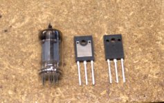
YEP, big mosfets. Big mosfets are usually big capacitors and thus not much use to us tube amp builders, but.....
What can dissipate 195 Watts, handle 7 amps continuous, 28 amps peak, eat 900 volts, and has only 7pF of Crss (the important spec for followers). OH, yeah it only costs $2.40.
I believe that the only place for a mosfet in a tube amp is a follower or a CCS. The only linear mode for a mosfet is a follower, and a mosfet follower can be more linear than a tube cathode follower. I have been using little tiny mosfets for followers to minimize the Crss. You also need to look for a CONSTANT Crss over the voltage range that the fet will see. Well, this big boy is between 7 and 8 pF for any voltage from 40 volts to 900 volts.
What is it....it is a Fuji 2SK3675.
Attachments
We ran in to a similar breakdown problem at work with TO-220 diodes used at the output of a power factor correction stage. The problem is that there is insufficient isolation between the screw, the tab, and the heat sink using the standard (short-shanked) shoulder washer for high voltages. A solution is to use a shoulder washer with a longer bit that extends all the way through the TO-220 tab into a counterbored hole in the heat sink. That way, one is assured of isolation between all the pieces involved. There are even insulators in the Bergquist catalog with a somewhat larger hole for the longer shoulder washer. All the pieces available through Digi-key (Bergquist, Keystone) for those who care to look. TO-247 parts don't have this problem because of the ring of epoxy around the mounting hole.
Last edited:
TO-247 parts don't have this problem because of the ring of epoxy around the mounting hole.
Visible in the picture I posted above. This is another reason I like the TO247 parts. Simplified mounting....no shoulder washer needed.
I usually use the insulated TO-220 since you just screw it to the heatsink, but most are only good to 35 watts. There are a few that are rated for 40, 45 or 47 watts. Touching one while it is operating at considerable power will tell you that the insulation is also an effective thermal barrier. They get hot.
- Status
- This old topic is closed. If you want to reopen this topic, contact a moderator using the "Report Post" button.
- Home
- Amplifiers
- Tubes / Valves
- TO220 isolation kits breakdown