Guys anyone have an idea of the right way to make a high frequency voltage amplifier using a pentode?
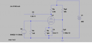
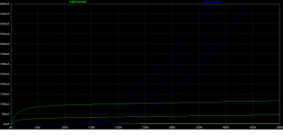
I am using 1 6146B beam power tube - the lab has given me this, i cant change it. and also a dc power supply of 460V. Following the book "Valve Amplifiers" by Morgan Jones i built an amplifier for 18 gain. I simulated this in LTSpice, it gives just 3.2 gain. The circuit and the pentode curves are in the attached figures. I have been calculating and reculculating for the past few days without avail.
Operating point=200V,100ma
Frequency=20MHz
I am using 1 6146B beam power tube - the lab has given me this, i cant change it.
and also a dc power supply of 460V. Following the book "Valve Amplifiers" by Morgan Jones i built an amplifier for 18 gain. I simulated this in LTSpice, it gives just 3.2 gain. The circuit and the pentode curves are in the attached figures. I have been calculating and reculculating for the past few days without avail.Operating point=200V,100ma
Frequency=20MHz
Attachments
Last edited:
What is the application? Do the people who have insisted that you use a 6146B know what they are doing? BTW I think that is a tetrode, not a pentode. Frequency, bandwidth, linearity, required efficiency? How much experience do you have of RF power design and construction? Any RF design and construction?
I don't want to rain on your parade, but I fear this project will end in tears. Even experienced people sometimes have trouble with valve RF PAs. You don't sound experienced.
I don't want to rain on your parade, but I fear this project will end in tears. Even experienced people sometimes have trouble with valve RF PAs. You don't sound experienced.
Hi Marcus. The power amplifier you ask, has some drawbacks. First, normally the act in resonant plate load, in which RDC is very low compared to RAC, so the model fails, also usually in RF circuits there exists a way to adjust the optimum plate load, example, a PI network, a tank with a link, etc.
Second, in normal operation, it works in Class C, that is, the plate current flows during a short period of time compared to the cycle. In that condition plate wasted power is much lower than in Class A. This, except in linear operation (For SSB) in where it works in Class AB usually.
And third, in power amplifier it is often more important power output or plate yield than signal gain. Finally, the power output also depends on frequency, and Q of the plate loading.
Good luck.
Here is a link to an article that is a pretty good expatiation of how an RF amp works.
ftp://ftp.ham.hr/Books/QEX/QEX20013.pdf
Start on page 32.
Here is a SE output class C RF amp with the schematic, and full details of the build.
Note the tuning network C3, C4, L3, L4 with L4 having taps for gross tuning.
The AA8V 6146B Amplifier - Amplifier Schematic Diagrams and Circuit Descriptions
Hey guys... I want to build a voltage amplifier, not a power amplifier. This is a physics project, the amplifier takes an input of 10V at 20MHz and should be able to give a 200V output at the same frequency. It is to be used as a driver for an electro-optic modulator. Could you please guide me on this?
I do not have any experience in RF design and construction.
I do not have any experience in RF design and construction.
You'll still need a tank circuit on the plate of that pentode tuned to 20MHz, and you need to know the impedance of what you are driving - despite the fact that you claim to be building a voltage amplifier you will need to deliver some power to the load in order to provide the 200V swing you need. First you need to figure out what the impedance of your electro-optic modulator and what are the components of that impedance both real and imaginary (reactive) - that will determine whether or not you need to deliver significant power to it. The fact that they gave you a specialized RF beam power tetrode is probably NOT a coincidence. You probably are building a linear amplifier... Take a look here: 6146B Beam Power Tube and Data Sheets
(Lots of RF power amplifier design information here)
http://faculty.frostburg.edu/phys/latta/ee/6146amp/6146b/6146b.html
(Lots of RF power amplifier design information here)
http://faculty.frostburg.edu/phys/latta/ee/6146amp/6146b/6146b.html
In these situations the actual requirement usually just trickles out of the OP, and may be different from what we assume/extrapolate from the first few drops of information. Apart from the silly capacitor values, the OP has drawn a video amp so maybe that is what he wants.
I would beging with the circuit like this.
I did not have the spice model for 6146, so I simulated with 6L6 and EL34 with quite similar results. In case of 6146 the screen voltage must be reduced.
C3 and C5 are variable capacitors. R4 and C6 simulates the load impedance.
An externally hosted image should be here but it was not working when we last tested it.
I did not have the spice model for 6146, so I simulated with 6L6 and EL34 with quite similar results. In case of 6146 the screen voltage must be reduced.
C3 and C5 are variable capacitors. R4 and C6 simulates the load impedance.
IMHO you could probably do the job with a tuned transformer then, no tube or power supply needed. However, going with the tube, to build a class A amp:The EOM is a pure capacitive load, the capacitance is in picofarads ( around 10 pF ). The output impedance of the signal source is 50 ohms.
Starting with your original circuit, I would replace Rp with a tuned circuit (coil and tuning capacitor in parallel) tuned to 20MHz. Now with the plate at 460V, if you bias G2 at 150V and use a 750 ohm cathode resistor, you should get about 40mA plate current and hopefully enough gain (assuming I read the curves right). The input resistor should probably be 50 ohms to match the cable.
There's nice info on the tube here: 6146B Beam Power Tube and Data Sheets
The input resistor should probably be 50 ohms to match the cable.
Why to lose some 12 dB gain which the input matcing circuit above gives ?
Artosalo, Thank you for the circuit. Godfrey thanks for the tips... That gives the necessary voltage at the output, but the circuit does not act as an amplifier. Irrespective of what the amplitude of the signal source is the output remains constant at the same voltage. I require a circuit that amplifies the input signal. Here it does not do that.
I am using 1 6146B beam power tube - the lab has given me this, i cant change it.
Operating point=200V,100ma
Frequency=20MHz
Passive resistive loading works at 20MHz and higher for solid state devices where you can drive up the gm to huge levels, and get useful gain with load resistors of under 100R. (This would require gm= 180mA/V) -- Not gonna work for hollow state where you don't have the gm. This is what makes "no tune" RF amps that can cover all ham bands possible.
A 20MHz hollow state amp like the one shown in the schemo will require an LC tuner of some sort: L-network, PI-network, singly or doubly tuned matching xfmr. These are required so that internal device capacitance gets "absorbed" into the tuning capacitance. That SS doesn't require LC tuning has made really good air variables harder and harder to come by.
As for the 6146, there will be no prob working it at 20MHz (almost any VT can do that -- hollow state does work at RF as well as it does at AF, and you don't have that beta-rolloff that you get with BJTs). You might possibly need some sort of neutralization to stop oscillations, and plate stoppers since this is a rather high gain VT.
As for how you design it: loadlines.
Guys anyone have an idea of the right way to make a high frequency voltage amplifier using a pentode?
I am using 1 6146B beam power tube - the lab has given me this, i cant change it.
Operating point=200V,100ma
Frequency=20MHz
Did they specify the input and output load impedances you must use?
I do RF design on a daily basis, and even work with tubes. While I rarely use SPICE programs, when I do the models are not reliable with tubes at higher frequencies. The models I have available neglect far too many things, plus I learned to do this in the 60's and 70's, long before SPICE and when tubes were still being produced. I am not your SPICE help at all.
That aside, it should be very easy to design and build an 18 dB gain amplifier provided they gave you reasonable source and load impedances (normally 50 or 75 ohms, or some fairly low resistance).
The voltage and current spec is reasonable, at 20 watts maximum plate input power you can't hurt the tube.
The starting point would require knowing the input power level or the output power level, and the input and output impedances.The EOM is a pure capacitive load, the capacitance is in picofarads ( around 10 pF ). The output impedance of the signal source is 50 ohms.
Are we talking about a "Q-switch"? A Q-switch is a quartz device used to control a laser beam. It is mounted inside the lasing path (between the mirrors). At rest the quartz is nearly transparent and offers little resistance to the light allowing laser action. As the Q-switch is excited with RF it begins to vibrate scattering the light beam reducing the lasers output. As the RF level is increased the scattering further reduces the laser output until the loss is enough to kill the laser action and then the whole system is just a very expensive light source.
If this is indeed the application, the Q-switch may appear to be a pure capacitance at rest, but it will take power to vibrate it and therefore become a lossy device. It is a quartz resonator operating at (or near) resonance.
The system that I maintained about 30 years ago had the RF matching components inside the Q-switch assembly such that the assembly was approximately 50 ohms input impedance. The system will radiate some of the RF power, and as such will have to meet regulatory compliance in the country of use. In most of the world the ITU has set aside "ISM frequencies" (industrial scientific and medical) where unlicensed emissions may occur. The two closest to "20 MHZ" are 13.56 MHz and 27.120 MHz. Verify the exact frequency before going too far.
The device that I worked with used a solid state amplifier that put out about 15 watts and operated at 27.120 MHz. These power levels are achievable with a 6146 tube.
We still don't know whether the 20MHz is CW or modulated, if so what bandwidth? Will the 6146 amp be modulated or should it be linear? We still appear to be in that early phase of a project where the customer does not know what he wants, so he can't ask the supplier how much it will cost.
- Status
- This old topic is closed. If you want to reopen this topic, contact a moderator using the "Report Post" button.
- Home
- Amplifiers
- Tubes / Valves
- RF Voltage Amplifier