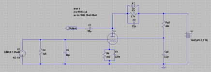
This circuit gives exactly what I want in LTSpice.. Voltage amplifier with 18 gain @ 20MHz. but is it the right to way to do it? I lose my operating point, which is 200v (dc) @ 100ma. This circuit works for 470 plate volts as soon as I put the shunt capacitance and the inductor in parallel with the load resistor (the reason I put the capacitor and inductor was to work at high frequency). How do i go ahead? Where am I going wrong.. How can I get back to my operating point with 18 gain and @ high frequency(20MHz)
Attachments
That circuit may "work" in LTSpice, but it almost certainly will not work in the real world. It looks like parts have just randomly been placed and adjusted to attempt a result without any planning.
Planning the circuit, the tube operating parameters would be set with DC voltages at each element. Then the input and output would be matched to the 50 ohm source and the specified load. The bandwidth needed would determine matching values.
Are you trying to learn how the system works, or how to fool LTSpice into the correct result by randomly changing parts values?
I expect that the whole point of the circuit is broadband operation. Simply modulating at a high frequency but with low bandwidth due to using bandpass tuned output would have no information carrying advantage over simply modulating with a amplifier that rolls of at a much lower frequency. The whole idea is to get more usable information bandwidth.
I figured a a trifilar-wound input transformer would make better use of the available drive power. With the three coils in series and the generator feeding the bottom third, the impedance would be raised by three squared to about 450 Ohms. With a 17 pF load, the 3 dB down point at the input would be around 20 MHz. With a small peaking inductor in series towards the grid capacitance, the response could be boosted just before rolloff (critical damping or slight underdamping).
With that gain of 3 at the input, the plate load could be lowered to a bit under 1K where the plate circuit bandwidth into the 10 pF circuit capacitance is similar to that of the grid circuit. A little inductance in series with the plate resistor could provide peaking as I described in the grid circuit. Unfortunately the operating point has to remain at fairly high bias current to get enough gm. If there were a way to get still more drive, I'd consider a 2:1 broadband stepdown transformer in the output to better drive a capacitive load. That would work best with a bit more plate voltage, and fixed bias to avoid wasting supply voltage at the cathode.
Last edited:
If amplifier needs to work with low impedance load, you can look at schematics of
HF communications amplifiers. They will be appropriate for that use. If impedace is very high and amplifier needs to cover full frequency range down to DC, find schematic of old tube based oscilloscopes. Vertical channel amplifier is what you should look at.
HF communications amplifiers. They will be appropriate for that use. If impedace is very high and amplifier needs to cover full frequency range down to DC, find schematic of old tube based oscilloscopes. Vertical channel amplifier is what you should look at.
The OP has thus far been unable or unwilling to say whether he needs a narrowband or broadband amp, and whether the 20MHz will be modulated. I suspect that he, and those setting the spec, don't actually understand what they are doing but I could be wrong!
This is the problem today when hiring recent grads. In the 1980's, about 10% of our EE interviews actually understood analog systems. That has steadily dropped.
At DC and low frequencies, tube models can be pretty close. At RF, tubes won't behave anything like any spice model. At least as far as any I have seen.
The circuit in question would depend on bandwidth and other things unknown. Like you say, maybe the person setting the spec is lost.
- Status
- This old topic is closed. If you want to reopen this topic, contact a moderator using the "Report Post" button.
- Home
- Amplifiers
- Tubes / Valves
- RF Voltage Amplifier