Dear Folks,
I try to build a head phone amp found schematic here:
http://www.roehrenkramladen.de/HBOSE8/HBOSE8.html
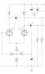
For tests I build only the LTP using matched 6922 because the values of Rb + Rk seemed to me unusual. I do not understand why Rb = Rk because all what I saw before was that Rb has a quite smaler value. Also a Bias of ~ 6.5V is really cold and on the right end of the load line.
I measued an imbalance of output signal of 4.2dB which seemed to me to high. I know, using a CCS will balance the LTP nearly perfect and I do not need matched tubes anymore. But I do not know if it "sounds" and also I would like to minimize the effort.
So, what is your opinion to the LTP dimensioning?
Do you have an explanation why the bias of the LTP is set to the cold end of the Loadline?
Thanks a lot for your help!
Best regards
Karsten
I try to build a head phone amp found schematic here:
http://www.roehrenkramladen.de/HBOSE8/HBOSE8.html
For tests I build only the LTP using matched 6922 because the values of Rb + Rk seemed to me unusual. I do not understand why Rb = Rk because all what I saw before was that Rb has a quite smaler value. Also a Bias of ~ 6.5V is really cold and on the right end of the load line.
I measued an imbalance of output signal of 4.2dB which seemed to me to high. I know, using a CCS will balance the LTP nearly perfect and I do not need matched tubes anymore. But I do not know if it "sounds" and also I would like to minimize the effort.
So, what is your opinion to the LTP dimensioning?
Do you have an explanation why the bias of the LTP is set to the cold end of the Loadline?
Thanks a lot for your help!
Best regards
Karsten
I do not see 'Rb' or 'Rk' in the schem, but assume you mean the resistors in the tail. Yes that seems very cold bias. Probably an attempt to get high impedance in the tail. With only 4k7 in the tail, the imbalance you measured sounds reasonable.
Using a PP transformer in the output kinda balances out any unbalance in the input stage, so I wouldnt worry about the lack of symmetry too much. If you do, a CCS (like you said) will do the trick.
Using a PP transformer in the output kinda balances out any unbalance in the input stage, so I wouldnt worry about the lack of symmetry too much. If you do, a CCS (like you said) will do the trick.
Hello,
Thanks for the answers. Sorry I mean R11 and R14 in schematic as you assumed. O.K. I assume I´m to sceptic concerning the impact of the imbalance. Otherwise this means that one of the both triodes driving the PP transformer will work more than the other.
If I build the complete schematic for one channel I will see what´s happens.
@SY:
I double checked the wiring an can´t find any mistake. Might be a good idea to use a CCS here to prevent any issues with the second stage. At now I used two transistors, two LED plus a high watt resistor as CCS in the tail. How to realize the same using (MOS)FET?
Thanks a lot!
Karsten
Hello SY,
GREAT Article! Thanks a lot for all these information!
Well, unfortunately the DN3545 ( wich is the current Version to use of the DN2540 ) is not available here in Europe Buy a few one at mouse.com will cost +20EUR shipping I hope I will find a similar FET, not really need full 450V Vds max.
An open question is how to dimension this kind of CCS. The difference is R5,R14 where R5 is 20mA and R14 10mA described in the text. But for a linear dependency I assumed R14 twice R5..
Regards
Karsten
GREAT Article! Thanks a lot for all these information!
Well, unfortunately the DN3545 ( wich is the current Version to use of the DN2540 ) is not available here in Europe Buy a few one at mouse.com will cost +20EUR shipping
I hope I will find a similar FET, not really need full 450V Vds max.An open question is how to dimension this kind of CCS. The difference is R5,R14 where R5 is 20mA and R14 10mA described in the text. But for a linear dependency I assumed R14 twice R5..
Regards
Karsten
Apparently, "FET" derives for the Sanskrit word for "variability."
You'll see quite a bit of variation in the required Vgs for a desired current for any FET, the DN2540 being no exception. I gave the values for the particular devices I had in my parts drawer, but you can easily see 3:1 variances from part to part. The model applies (one hopes!) to the center of the range.
You'll see quite a bit of variation in the required Vgs for a desired current for any FET, the DN2540 being no exception. I gave the values for the particular devices I had in my parts drawer, but you can easily see 3:1 variances from part to part. The model applies (one hopes!) to the center of the range.
Hello folks,
Sorry for digging out this thread!
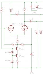
Now I´m using a CCS as recommended by SY. But I used the "old style" to prevent selecting matching FET which are also hard to get here and using transistors plus LED´s.
The balance is now realy good but unfortunately the gain of the LTP increased by +6dB. The original circuit has a gain of 15dB, using a CCS I get 21dB. I moved the working point from the right "cold" end of the loadline to the middle. Now Ik is 6mA and bias is 2,18V.
This is what i never expected
Why the gain is now increased? And how to reduce the gain back to 15dB?
Thanks a lot to enlight me...
Regards
Karsten
Sorry for digging out this thread!
Now I´m using a CCS as recommended by SY. But I used the "old style" to prevent selecting matching FET which are also hard to get here and using transistors plus LED´s.
The balance is now realy good but unfortunately the gain of the LTP increased by +6dB. The original circuit has a gain of 15dB, using a CCS I get 21dB. I moved the working point from the right "cold" end of the loadline to the middle. Now Ik is 6mA and bias is 2,18V.
This is what i never expected
Why the gain is now increased? And how to reduce the gain back to 15dB?
Thanks a lot to enlight me...
Regards
Karsten
Attachments
The low bias in your first attempt provides very little gain. That tube enjoys a bit more current than other higher mu types. The gain you get now is what to expect when the tubes are properly biased. (Look at the datasheets and how the Gm/rp/mu is at low ib say 1mA, compared to higher, say 5mA).
The imbalance you had is also what to expect with such low impedance tail, but like I said, it's actually not so important b/c the transformer will naturally balance the final output signal.
To lower gain you should reduce the plate resistor to 10kohms, which this tube handles fine. But do you need to lower the gain? You may also include some cathode resistance, but make sure they don't eat up the voltage you need for the tail.
Btw, now that you are at 6mA, contra 1 or so, you should note the larger voltage drop over the 4k7 resistor in the supply. It now drops some 30V. Yet another reason to go to 10kohm plate resistors.
Last edited:
Now that you are going active tail, perhaps you want to try a CCS that can take a little lower voltage, and get rid of the input capacitors?
With an opamp and a transistor you can get down to a very low voltage, but your LTP has some 3volts to play with if grids are grounded. A simple JFET CCS can do the trick. It is not a precision CCS and will evoke emotions among the nitpickers, but the simplisity and the removal of the caps, make it tempting?
Just a suggestion:
edit: I should add the cathode resistors are merely serving as HF stoppers in addition to the grid stoppers, thus the low ohmic value. Not much room for larger values b/c the ccs needs all available voltage.
Attachments
Hey SemperFi
Thank you so much for your help and suggestions! I see that´s never to late to learn more and more about valves...
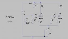
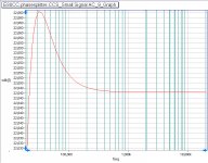
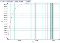
So I simulated both variants using B2Spice ( It´s more intuitive usage than PSpice for me ) and also using datasheed from ECC88 ( Phillips ). Conclusion is:
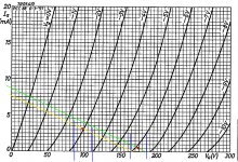
Taking datasheed as basis I should assume a delta Ukathode of 2dB between verry cold working point (Green loadLine ) without CSS and middle positioned (Yellow loadLine) . Using none CSS I "lost" 10V in the tail but 34V if I use the CSS version.
Taking in account that the following PP stage is AC coupled this should not matter.
If I simulate both circuit variants I get a quite similar result. Using CSS the gain increase round about 2dB than without CSS.
In the reality my circuit increase the gain of 6dB. So first I have again double check my wireing and values of the components. Definitive I must handle the 4K7 in the supply chain. It´s originally used as an R/C ripplerejection from PSU. I will youse a Madia PSU for that I think I can remove this part of the circuit.
At least you are completly right that the transformer will remove every imbanace of the phase splitter. Nevertheless it´s a goot training session for me to try to make the phasesplitter as best as can.
Also I will try to check your proposal using only one FET as CCS.
Thanks a lot and... How is the wather in wake island
Karsten
Thank you so much for your help and suggestions! I see that´s never to late to learn more and more about valves...
So I simulated both variants using B2Spice ( It´s more intuitive usage than PSpice for me ) and also using datasheed from ECC88 ( Phillips ). Conclusion is:
Taking datasheed as basis I should assume a delta Ukathode of 2dB between verry cold working point (Green loadLine ) without CSS and middle positioned (Yellow loadLine) . Using none CSS I "lost" 10V in the tail but 34V if I use the CSS version.
Taking in account that the following PP stage is AC coupled this should not matter.
If I simulate both circuit variants I get a quite similar result. Using CSS the gain increase round about 2dB than without CSS.
In the reality my circuit increase the gain of 6dB. So first I have again double check my wireing and values of the components. Definitive I must handle the 4K7 in the supply chain. It´s originally used as an R/C ripplerejection from PSU. I will youse a Madia PSU for that I think I can remove this part of the circuit.
At least you are completly right that the transformer will remove every imbanace of the phase splitter. Nevertheless it´s a goot training session for me to try to make the phasesplitter as best as can.
Also I will try to check your proposal using only one FET as CCS.
Thanks a lot and... How is the wather in wake island
Karsten
Attachments
- Status
- This old topic is closed. If you want to reopen this topic, contact a moderator using the "Report Post" button.
- Home
- Amplifiers
- Tubes / Valves
- Imbalanced LTP using 6922/E88CC