Hi, I've got a Chinese amp here (Yaqin) and the only caps in the signal path are the coupling caps between the PI and the power tubes. The caps they used look to be these Pilkor (Philips) caps.
Do you think a noticable improvement could be made by changing these out for a higher quality cap? The sound is actually quite good, but could an upgrade remove any residual graininess to the sound? Any recommendations? Thanks.
Do you think a noticable improvement could be made by changing these out for a higher quality cap? The sound is actually quite good, but could an upgrade remove any residual graininess to the sound? Any recommendations? Thanks.
Thanks for the reply,
is it worthwhile to change them in your opinion?
DHT112A is right! you should use the right ones for audio like:
Sonicap,Auricap,Mundorf etc
")
Do you think they used X2's because they will fail open, and not shorted?
More like they were the right price.
More like they were the right price.
Perhaps, but I think regular film caps would source cheaper than safety caps. There's no other advantage to using these?
Hi rntlee , it would be better to make some improvements in the circuit of the amp , if you want I will try to help you .Thanks Dimitris,
I think that sonic improvement would be pretty minimal vs. cost, so I'm going to leave them be. Plus they have the added benefit of protecting the grid of the El34's in the event that they should fail!
These are Meatlaised Polypropylene caps.
Polyproylene Film/Foil may give a marginal improvement in performance if you have them already in your parts bin. If not, I would leave them alone.
Cheers,
Ian
Thanks Ian,
I am going to leave them be for now.
( I know you wanted to type metalized!
)Hi rntlee , it would be better to make some improvements in the circuit of the amp , if you want I will try to help you .
I would be interested in your opinion of the circuit. I've got a schematic...it's got a couple of errors (R120 is in the wrong spot, R107 is actually R127 on the board) Here's the schematic I have:

I measured a few voltages referenced to ground and marked where R120 actually is in this partial schematic:

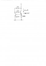
Humm!! 345V - 225V = 119V across 68K is 1.8 mA
2 times that (for each of V103 and V104) = 3.6mA
Not sure how you came up with 6mA.
If you make this change (adding the current source) it will also be necessary to change the anode loads to be equal, make them both 68K.
Cheers,
Ian
2 times that (for each of V103 and V104) = 3.6mA
Not sure how you came up with 6mA.
If you make this change (adding the current source) it will also be necessary to change the anode loads to be equal, make them both 68K.
Cheers,
Ian
Modifications
Increase capacitors C106,C111, C112 to 100μF( or higher ), make R119 and R120 -10ΚΩ 5W and R109, R129 - 33KΩ 2W , and you can remove the two capacitors ( as shown in the schematic ) C101 220μF , this will decrease the gain but the amb will sound more cleaner due to the lack of any electrolytic caps in the signal path .
Increase capacitors C106,C111, C112 to 100μF( or higher ), make R119 and R120 -10ΚΩ 5W and R109, R129 - 33KΩ 2W , and you can remove the two capacitors ( as shown in the schematic ) C101 220μF , this will decrease the gain but the amb will sound more cleaner due to the lack of any electrolytic caps in the signal path .
- Status
- This old topic is closed. If you want to reopen this topic, contact a moderator using the "Report Post" button.
- Home
- Amplifiers
- Tubes / Valves
- cap upgrade worth it?