Folks,
I'm trying to understand something here.... I've been messing with a 300B amplifier design for 2+ years now and am now back to square one. My current design sounds too harsh for my taste.
Output stage: There are several options for biasing a 300B (or any other DHT for that matter). Some people swear that one topology sounds better than another. I'm trying to understand what would cause the difference.
For the sake of simplicity, I'm limiting the options to three; fixed bias, cathode bias, and Loftin-White (cathode bias but with the cap to B+). Attached shows the schematic for the three. I have considered using a CCS, but that opens up a different can of worms.
I intend to set up a test bench for all three configurations and try them one by one. For those of you who have already made this experiment, what were your findings?
~Tom
Attachments
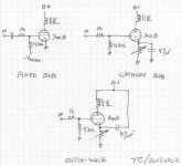
IMO, you need to add a 4th option to your list, combination bias.
The advantages of combination bias include: resistance to runaway, a reasonable amount of heat generation in the cathode resistor, and (if the smallish cathode resistor is unbypassed) some linearization of the O/P tube. The 2A3 is more linear than the 300B. Remember that Harvey Rosenberg, a lover of the type, unambiguously stated that 300Bs put on a show.
DHTs are vulnerable to runaway. When simple "fixed" bias is employed, a small value is essential in the grid resistor value.
Combination bias? So some amount of the Vgk is by dropping voltage across a cathode resistor and the rest applied to the grid? That sounds intriguing. How much of the total bias would you suggest to apply by cathode and fixed bias respectively, then? Like 80/20 split between fixed/cathode? What's a good starting point?
~Tom
~Tom
100 Ω as the cathode resistor makes setting the "idle" current a cinch, but might not provide enough protection against runaway. 150 Ω is not especially difficult as a test point from a math perspective, while offering a fair improvement in the runaway protection dept.
It is possible to cap. bypass a portion of the total cathode resistance. That allows for superior stabilization of the operating point, without an excessive increase in the effective RP from local current NFB (degeneration). 100 Ω bypassed by 470 μF. stacked on top of an unbypassed 100 Ω might be a very effective setup. There's plenty of protection against runaway, the math is easy, and the amount of degeneration reasonable.
It is possible to cap. bypass a portion of the total cathode resistance. That allows for superior stabilization of the operating point, without an excessive increase in the effective RP from local current NFB (degeneration). 100 Ω bypassed by 470 μF. stacked on top of an unbypassed 100 Ω might be a very effective setup. There's plenty of protection against runaway, the math is easy, and the amount of degeneration reasonable.
I've just been doing some 300b biasing. I had insufficient HT, so I had to look at combination bias. Right now I have 388v on the 300b anode, 24v on the cathode with a 407 ohm cathode resistor bypassed with a 100uf polypropylene cap. 60mA of current, so 364v a-k and 21.5W dissipation. The 300b is fed by a 46 driver through a 126C Hammond interstage, and the bias voltage is applied to the bottom of the 126C secondary. Very good interstage, incidentally.
At the same time I was biasing the input stage I looked at biasing the 46. Battery grid bias was clearest, but not as smooth as cathode bias. However, bypassing the cathode on the 46 was not successful. There was a small gain in clean treble, but that was very much offset by a monotonous blurring of the whole sound - the harmonics and timbre of acoustic instruments were less rich, and the whole sound was frankly boring. An electrolytic was worst (quite awful) and a polypropylene cap was better but still nowhere near as involving for the listener as no cap. Bypassing the cap with smaller teflons made no difference.
So I'd say the worst choice would be cathode bias with an electrolytic. For the output stage bypassing with a good film cap is acceptable, but I would look for other options for input stages. For the bias supply itself, I'm not satisfied. Just a cap resulted in a slightly shrill treble. CRCRC with electrolytics and 1K resistors was a little better but treble still dirty. Changing the last cap to a 47uF polypropylene was better, but treble still not silky smooth. I currently have UF4007 diodes, but no doubt schottkys would be better. So as I say, I'm not satisfied with the bias supply yet. I actually posted this week on this subject but got no useful replies. I've seen an EZ81 choke input supply used for this, and some have used batteries (!!!). So as things stand, I'd go with cathode bypass with a polypropylene cap (NOT electrolytic). With combination bias the sound is clean with good bass, but this may be due to other factors.
For my preamp I use filament bias which is the best I know. Look at the "26 pre amp" thread - posts around 1 and 2 March where Rod Coleman suggests a way of using filament bias with bigger tubes like 46. Maybe 300b - haven't considered this. But I will say that even with Rod Coleman's brilliant filament supply boards which are now widely used, I like to add choke input to the supply.
Andy
Last edited:
Andy,
I agree that film caps are preferable to electrolytic caps in many cases, though, I've had good experience with the Nichicon KZ-series of audio electrolytic caps. They don't come in very high voltages, though. Currently, I'm using some Solen 47 uF, 630 V polypropylene caps.
I'm familiar with Rod's filament regulator. Personally, I've gone the switchmode route (see my website). I've tried both constant voltage and constant current. I've never been able to tell a difference between the two in listening tests or measurements and constant voltage is less expensive and much more efficient (especially when using switchers). So I went that route. But filament regulators are a different can of worms. One can at a time...")
I think I'll get my butt into my lab and wire up some circuits. I'll keep you posted. Thanks for your input.
~Tom
I agree that film caps are preferable to electrolytic caps in many cases, though, I've had good experience with the Nichicon KZ-series of audio electrolytic caps. They don't come in very high voltages, though. Currently, I'm using some Solen 47 uF, 630 V polypropylene caps.
I'm familiar with Rod's filament regulator. Personally, I've gone the switchmode route (see my website). I've tried both constant voltage and constant current. I've never been able to tell a difference between the two in listening tests or measurements and constant voltage is less expensive and much more efficient (especially when using switchers). So I went that route. But filament regulators are a different can of worms. One can at a time...
I think I'll get my butt into my lab and wire up some circuits. I'll keep you posted. Thanks for your input.
~Tom
I've never built an SE am so feel free to ignore me, but maybe some of my experiences will help. I did an experiment a few years ago where I built a push-pull amplifier with triode-connected KT88s. I drove them with direct coupled mosfet followers but grid current was limited with a 1k stopper at the KT88 grid. Fixed bias was applied to the gate of the mosfets. I cranked up some music, turned the volume way up, and watched amp output on a scope. The music was really up loud and I would didn't sound perfect but I thought it was pretty good. Shockingly, the amplifier was grossly distorting (I was well into clipping I could see on the scope) but still sounded decent, not great but not nearly as bad as I thought it would have by looking at the scope. I became a big fan of instantaneous overload recovery that day.
I later built a unity-coupled push-pull amp (McIntosh output circuit) and as a result of my driver design and the huge drive requirements I had a lot of 2nd harmonic in the amp output(for a push-pull amp). The amp measured well otherwise and I think I actually asked you at the time what you were getting for THD from your 300B amp and it was similar to what this amp was putting out at 1W. The problem is, when I played an electronic-type song with female vocals (very complicated song), the 's' sounds in the vocals just sounded off. I was guessing that it was just the bent transfer characteristic of the amp making IMD with complex music. I am in the process of rebuilding that amp right now and am trying to really get that transfer characteristic straightened up so that I can listen to things other than 'lady singing with piano'.
I would start with the question of why the current amplifier sounds harsh by taking some measurements (maybe you already did this, but really characterize the behavior of this thing) and try to address whatever the problem is. You could have an overload recovery issue or maybe you listen to interesting music and hate IMD, who knows?
Folks,
I'm trying to understand something here.... I've been messing with a 300B amplifier design for 2+ years now and am now back to square one. My current design sounds too harsh for my taste.
Output stage: There are several options for biasing a 300B (or any other DHT for that matter). Some people swear that one topology sounds better than another. I'm trying to understand what would cause the difference.
For the sake of simplicity, I'm limiting the options to three; fixed bias, cathode bias, and Loftin-White (cathode bias but with the cap to B+). Attached shows the schematic for the three. I have considered using a CCS, but that opens up a different can of worms.
I intend to set up a test bench for all three configurations and try them one by one. For those of you who have already made this experiment, what were your findings?
~Tom
I haven't tried the 3rd option but, at least on chart, using a good driver tube could be better than the other two but I can't tell for sure.
I wouldn't choose any of the other two. I would rather use a direct-coupled cathode follower. It is not so complicated if you don't demand too much in terms of positive grid drive. Many Audio Note amps use this solution but don't really use positive grid operation so much, just a little bit.
The reason for this is strictly related to the 300B and similar power tubes, not all them though. The 300B looks really good on chart but is quite demanding in terms of driving. All troubles and "hard work" are on the driver. If you think that one pair of 2A3's in parallel has total 30W plate dissipation without any problem, about 10000 umhos transconductance, 400 ohms internal resistance and no more than 110V peak-to-peak for light A2 drive is required you can see the difference! I guess the harsh sound you talk about is related to the driver. No matter what driver and bias you choose a 470K grid resistor and a coupling cap are not good enough for me. It's really a no-no...
Cheers,
45
Last edited:
I would rather use a direct-coupled cathode follower. It is not so complicated if you don't demand too much in terms of positive grid drive.
Personally, I prefer a source follower for this. No issues with grid drive....
The 300B looks really good on chart but is quite demanding in terms of driving. All troubles and "hard work" are on the driver.
No kidding!
I guess the harsh sound you talk about is related to the driver.
Or the speaker, actually...
I've never built an SE am so feel free to ignore me, but maybe some of my experiences will help. [.....] I became a big fan of instantaneous overload recovery that day.
Your input is always welcome. Yeah... I too have experienced the nasty effects of blocking distortion. That's what happens when the DC coupling cap to the 300B discharges during a transient, thus, moving the DC bias point of the 300B on recovery. It causes the speakers to emit some really rude sounds. Hence, my use of source followers as well.
However, with the present setup where I'm driving my 300B through an LME49811-based amplifier with 120 Vpp, 5+ A current capability blocking distortion is really not an issue...
The amp can't actually deliver enough voltage swing to drive the 300B into A2.I was guessing that it was just the bent transfer characteristic of the amp making IMD with complex music.
Do you happen to have measured data for the IMD? I don't... But it would be interesting to see.
I would start with the question of why the current amplifier sounds harsh by taking some measurements (maybe you already did this, but really characterize the behavior of this thing) and try to address whatever the problem is. You could have an overload recovery issue or maybe you listen to interesting music and hate IMD, who knows?
Well... I hooked up my sand amp. It's based on an LME49811 and is about as low THD as modern sand allows. 0.005 % THD up to clipping, basically. I still get the harshness to the sound - though not as much as with the tube circuit I had yesterday. So I suspect much of the harshness is due to the speaker. But I think I'd have to measure the woofer and tweeter separate to figure that out. It's possible that either is emitting rude sounds during the crossover transition.
~Tom
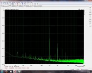
So... I took some measurements
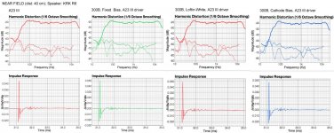
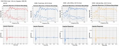
Setup: JJ 300B in the configurations listed in Post #1 driven by my sand amp. I call it A23 III as it lives in the chassis of a Parasound A23 that suffered water damage. I reused the power supply and built an amp to fit the chassis. The A23 III is documented in This Thread.
The two images show far field and near field measurements using a Dayton EMM6 microphone. Near field is 40 cm from the speaker with the microphone centered vertically between the woofer and tweeter and centered horizontally on the speaker front. Far field is about 20 cm forward of my usual listening position - about 140 cm from the plane intersecting the speakers. The closest wall is 170 cm away and the second closest is 200 cm away from the left speaker - the one used in this measurement. The speakers are 90 cm from the carpeted floor. The room is about 20 m^2 with an opening into the kitchen (15 m^2). The room is relatively live, though, I've never measured the reverb time.
Before listening tests I ran a quick test on my distortion analyzer (HP 8903A). The three 300B setups measure identically.
The Loftin-White and Cathode Bias circuits sound very close, if not identical, to each other. If I was to pick a difference between the two, I'd say that the cathode bias has slightly muddy highs compared to the Loftin-White. I found both the Loftin-White and Cathode Bias somewhat boomy in the bass and kinda tense to listen to. The fixed bias is an improvement over the previous two in my opinion. The difference is not huge, but I find the highs more enjoyable and precise. It seems more precise overall.
So, it seems the bias configuration of the output stage matters a little bit but not greatly. The fixed bias does have the distinct advantage that B+ is lower and the parts cost of the bias circuit is a handful of 10-cent resistors and a small trimpot.
~Tom
Attachments
Or the speaker, actually...
~Tom
Of course, the choice of the speaker is important if you want to use SE amps in general but most of times, especially with harder-to-drive speakers, the weakness of the driver will come before the full capability of the 300B is reached.
Cheers,
45
The fixed bias is an improvement over the previous two in my opinion. The difference is not huge, but I find the highs more enjoyable and precise. It seems more precise overall.
So, it seems the bias configuration of the output stage matters a little bit but not greatly. The fixed bias does have the distinct advantage that B+ is lower and the parts cost of the bias circuit is a handful of 10-cent resistors and a small trimpot.
~Tom
Well, I think you need a better bias supply than that. I agree that fixed bias (in my case combination bias) had the clearest sound and by far the best bass compared to cathode bias, but I wasn't satisfied with a slightly dirty treble. A film cap as the last cap seems a requirement for the sound quality - this was audible - and no doubt Schottky diodes. As for what else would improve it I'm open to suggestions because this is potentially a good option.
andy
Well, I think you need a better bias supply than that. I agree that fixed bias (in my case combination bias) had the clearest sound and by far the best bass compared to cathode bias, but I wasn't satisfied with a slightly dirty treble. A film cap as the last cap seems a requirement for the sound quality - this was audible - and no doubt Schottky diodes. As for what else would improve it I'm open to suggestions because this is potentially a good option.
I really like the sound of this fixed bias circuit. I agree that the highs could use a little clean-up, but the sound stage is awesome. As is the presentation overall.
Today, I'll add a source follower to it. Probably a 2SK3564 as it has the lowest gate capacitance among the high-voltage devices I've been able to find. That will make the driver's job much easier. Currently, I've cap coupled the grid of the 300B. As my driver isn't capable of driving the 300B into saturation (my 150 W sand amp "only" has a 50-ish Vp output voltage swing) I don't have issues with blocking distortion. But the driver also can't source any grid current as the DC coupling cap gets in the way. I'll build it up and post results.
As far as the quality of the bias circuit goes... I'm not looking to start a religious shouting match about this brand of boutique resistors versus that brand of boutique resistors.
Now, I do agree that the parasitic components present in any component can play a role in the perceived sound quality. This is why I tend to use metal film resistors. I've measured the 10-cent metal films commonly available and found them to be "flat" (resistive) up to 40 MHz (the upper limit on the impedance analyzer). I also tend to use polypropylene caps as they don't suffer (as much if at all) from dielectric absorption and the good ones have extremely low ESR, resulting in an extremely low loss tangent. Again, I have measured these parameters using an HP 4194A impedance analyzer and compared with the manufacturer's specs. The Solen caps I have meet the published specs... 47 uF, 630 V, 5 mOhm ESR confirmed. That's impressive!
So I tend to base my component choices on data... I realize that few people have access to the test equipment needed to confirm the manufacturer's data, but everybody has access to the manufacturer's data... If the manufacturer chooses to publish it, that is. If they don't... Shop elsewhere. That's for me anyway. Others are free to be different.
~Tom
2 pF low enough?
http://aosmd.com/res/data_sheets/AOT1N60.pdf
785-1184-5-ND 72 cents each at Digikey.
http://aosmd.com/res/data_sheets/AOT1N60.pdf
785-1184-5-ND 72 cents each at Digikey.
Reverse transfer capacitance (Crss), not gate capacitance, is the critical parameter for a FET performing voltage follower duty. Select a part whose Crss is both low and stable.
Tru dat. Thanks for being more specific than I was. Yeah... The gate-source cap shouldn't matter as the source voltage follows the gate voltage. And as the drain sits at AC ground, it's the raw drain-gate cap (Crss) that's important. No miller effect as the drain is at AC ground.
2 pF low enough?
http://aosmd.com/res/data_sheets/AOT1N60.pdf
785-1184-5-ND 72 cents each at Digikey.
That's seriously impressive. Thanks, George!
The sound (mainly the highs) has cleaned up quite a bit with the source follower. Still can't measure a difference, though. Neither on the test bench nor in front of the speaker. At least not in the frequency or impulse response. I haven't measured the power response.
~Tom
Last edited:
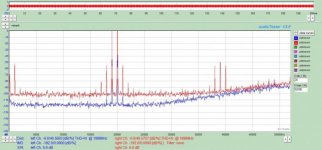
Do you happen to have measured data for the IMD? I don't... But it would be interesting to see.
I just remembered I was going to post this days ago. Sorry, I was figuring out how to use ARTA so levels aren't the best here and I didn't know how to get it to compute the percentage for IMD. I don't know if the frequencies/ratios I used for this are the best/most standard. I was just playing around at this point.
Attachments
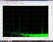
I don't know if there is a formal standard for IMD measurements. There probably is, but I'm not really a standards person... Most measurements I see of IMD use 9 kHz and 10 kHz at -3 dB of full power and measure the 1 kHz IMD component.
I swapped the 2SK3564 for the AOT1N60 that George suggested for the source follower. The jury is still out for the final verdict, but initial impressions are good. With the 2SK... I was getting rather 'tense' highs (for lack of a better word) and lots of fizziness on metallic percussion instruments. All this seems gone now and replaced by a much more balanced sound. I wish I could correlate this with measurements, but no dice (not that I really tried that hard).
~Tom
Most measurements I see of IMD use 9 kHz and 10 kHz at -3 dB of full power and measure the 1 kHz IMD component. I swapped the 2SK3564 for the AOT1N60 that George suggested for the source follower. The jury is still out for the final verdict, but initial impressions are good. With the 2SK... I was getting rather 'tense' highs (for lack of a better word) and lots of fizziness on metallic percussion instruments. All this seems gone now and replaced by a much more balanced sound. I wish I could correlate this with measurements, but no dice (not that I really tried that hard).
~Tom
- Status
- This old topic is closed. If you want to reopen this topic, contact a moderator using the "Report Post" button.
- Home
- Amplifiers
- Tubes / Valves
- 300B (or other DHT) biasing options