Hey everyone, just a general question on power tubes...most of the power tube data sheets I see tend to have the screen voltage a good 50 volts below the plate voltage yet 99% of the time I see tubes in real applications they're only running a couple volts below the plate...how critical is this voltage? Would performance/efficiency/tube life be increased at all by getting these voltages closer to the theoretical value or is "a little bit less than plate voltage" good enough. Thanks.
In a pentode, anode current is most defined by screen voltage, the anode voltage is less important defining the plate current. Such important is the screen voltage, that this value divided voltage at grid #1 (Signal) defines the cut off current by a coefficient called g2/g1 mu value. Anode voltage defines few % of the cut off current. Normally, the screen must be at or under plate voltage, but practically because of transformer primary resistance, in turn it is plate voltage less than screen.
Screen voltage doesn't need to be far below the plate voltage, as long as you're not above the maximum. The datasheets likely also tell you that max plate voltage is typically higher than screen grid voltage. If you tie the screen grid directly to the plate then obviously you'll be putting the pentode into triode mode, but a fixed voltage slightly lower than the plate is normal, as you've seen. Tube life would be a question. Screen grids have a maximum dissipation wattage, just like plates that you need to be careful with.
I've been contemplating a new pentode design and would like to add to your question (hopefully not a highjack) and ask, what effect on tone would there be with different plate to screen grid voltage differentials? ie, how would the amp sound with screen = plate - 10V, vs screen = plate - 100V?
I've been contemplating a new pentode design and would like to add to your question (hopefully not a highjack) and ask, what effect on tone would there be with different plate to screen grid voltage differentials? ie, how would the amp sound with screen = plate - 10V, vs screen = plate - 100V?
doozerdave: I don´t know about sounding because i´m not a musician, but surely the screen voltage affects directly to plate current, and transconductance. So gain will be different, possibly lower than with normal screen voltages approximate equal to plate voltages. I don´t know how it can modify sound quality.
Perhaps I'll experiment with it then. I have a spare power transformer that I want to use in a single ended pentode design, but it's 700Vrms (at 115V primary), which is giving me 500Vdc because I have 123V mains in my house. I want to use a 6550a or EL34 (interchangable), so I need to be careful how I design this.
Anyway, I don't want to high jack with that topic.
Anyway, I don't want to high jack with that topic.
Difference in screen voltages changes shape of plate curves. For higher currents on lover anode voltages of course you want higher G2 voltages. But the drawback is, when anode voltage goes down with current G2 current starts going up sharply. G2 can be overheated and damaged. What matters, peak and average power dissipation of screen grids. Max screen grid current and max power dissipation are usually specified by manufacturers. Voltage does not matter, it is up to you to decide what is the best compromise between shapes of curves and reliability. Lower G2 voltage can be good as well for high swing linearity when the tube is loaded on high resistance. I usually stabilize G2 and G1 voltages of output tubes by solid state regulators.
Last edited:
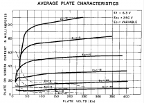
There have been many comments online advising against operating a pentode with Vp much less than Vg2, yet on the data sheet curves posted below for example, one of the most linear operating points is with Vg2=250V and Vp=162.5 with a load line drawn from 100mA to 350V = 3500Ω. In a circuit where trying to get the most power out possible is not a consideration is this operating point still a bad idea and if so, why?
Thanks!
Thanks!
Attachments
Higher screen voltages = higher screen currents, more power wasted in screen, and more screen stress.
Higher screen voltages = lower plate resistance and lower optimal load resistance.
Power pentodes are more linear, sound better, and are more reliable (due to limited screen dissipation) with Ua>>Ug2, but under such condition the optimal load resistance (the one resulting in the lowest 2nd harmonic) may be rather high. For example, optimal loads for PP 807 stage:
Ua=300 V, Ug2=300 V, Rl=6K
Ua=750 V, Ug2=300 V, Rl=12K
on the data sheet curves posted below for example, one of the most linear operating points is with Vg2=250V and Vp=162.5 with a load line drawn from 100mA to 350V = 3500Ω. In a circuit where trying to get the most power out possible is not a consideration is this operating point still a bad idea and if so, why?
Look at screen current. When control grid swings towards zero volts, plate voltage goes down and screen current dramatically increases. Under the regime that you propose, there will be a lot of wasted power in screen and screen will melt quickly at full output.
OK then, two more questions.
So as long as the driver is set up not to push Vp to less than ≈50V it would be OK?
Yes, but remember that power is square of voltage, and what you are proposing is to reduce voltage swing from 300 V to 200 V. Power will be reduced 2.25 times.
If you were going to build based on these curves, where would you set your operating point?
Ua=250 V, Ug1=-15V
Last edited:
hey-Hey!!!,
The g2 sets the envelope under which the tube operates w/o g1 current. Your job is to keep the load line out of where the load line bunches up on the g1 curves. It is quite OK to put signal onto the g2( U-L, CFB from a fixed voltage, and... ) Modulating g2 in a way that only approximates the signal based on its g2 current is not usually a good thing IME. It is called the 'Screen Grid' for good reason; use that feature to best advantage...")
cheers,
Douglas
The g2 sets the envelope under which the tube operates w/o g1 current. Your job is to keep the load line out of where the load line bunches up on the g1 curves. It is quite OK to put signal onto the g2( U-L, CFB from a fixed voltage, and... ) Modulating g2 in a way that only approximates the signal based on its g2 current is not usually a good thing IME. It is called the 'Screen Grid' for good reason; use that feature to best advantage...
cheers,
Douglas
What you say makes sense but I find it hard to opt for a higher power output that so clearly nets higher distortion. Am I wrong?
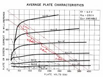
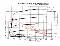
(The two sheets below show the lower 3K5 and higher 6K25 load lines and how they balance out either side of the operating point.)
Does it not make sense to choose the lower distortion operating point and then design a driver stage that doesn't push it into the rising g2 current zone ?
(The two sheets below show the lower 3K5 and higher 6K25 load lines and how they balance out either side of the operating point.)
Does it not make sense to choose the lower distortion operating point and then design a driver stage that doesn't push it into the rising g2 current zone ?
Attachments
If your g2 supply can deal with the higher g2 current( and the valve can handle the dissipation ), I am not seeing a problem. The driver should be able to drag the grid where ever it wants( grid current included if so desired ).
Both of those load lines should be used with a lower g2 voltage, the right one much lower.
cheers,
Douglas
Both of those load lines should be used with a lower g2 voltage, the right one much lower.
cheers,
Douglas
- Status
- This old topic is closed. If you want to reopen this topic, contact a moderator using the "Report Post" button.
- Home
- Amplifiers
- Tubes / Valves
- Importance of Screen Voltage of Pentode???