I saw a 6P3P SE shecmatic yesterday. It's the circuit for a famous Local brand amp. This model has very good feedbacks.
I'm very courious why it has 2 feedbacks, one from the transformer output and one from the plate of 6P3P. Can anybody tell me what's the benefit of this design?
I'm very courious why it has 2 feedbacks, one from the transformer output and one from the plate of 6P3P. Can anybody tell me what's the benefit of this design?
Attachments
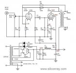
The loop from the output tube plate lowers the source impedance driving the output transformer. This helps to maximize the transformer's performance.
The loop from the secondary of the transformer helps to linearize the characteristics of the transformer itself, thereby helping to diminish any negative contributions it makes to the amplifier's overall performance.
Dave
The loop from the secondary of the transformer helps to linearize the characteristics of the transformer itself, thereby helping to diminish any negative contributions it makes to the amplifier's overall performance.
Dave
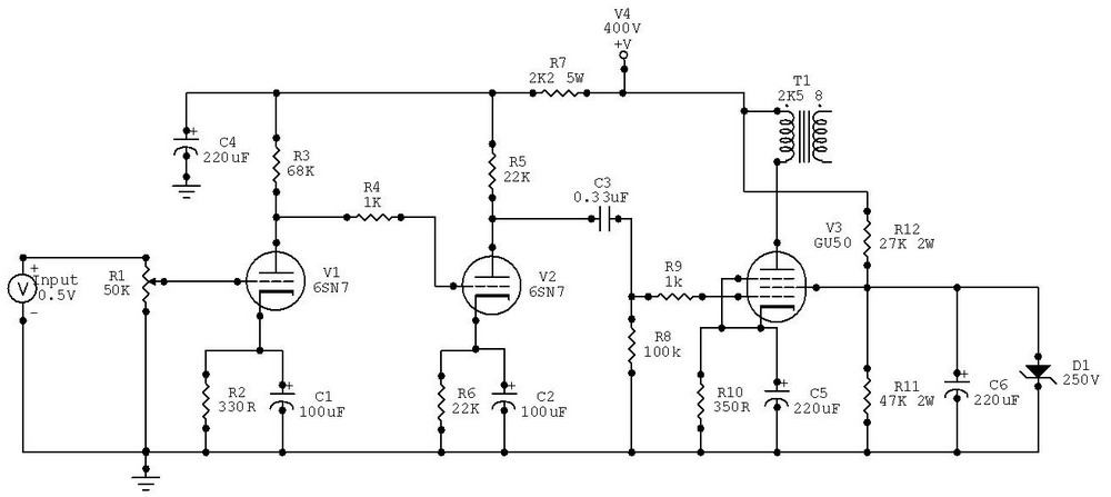
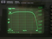
I measured some transformers with HP3563A these days. The freq response will drop 3dB when the frequency is over 30 or 40kHz. I understand that the feedback can deal with the drop. But in some circuit (like the GU-50 below), there's no global feedback, how can it deal with the freq response drop of the transformer?
Attachments
That means a better transformer is needed for circuits without feedback, the price difference must be 100 times than a feedback resistor.
Basically that's what drove consumer audio circuit development until we ended up with magnavox consoles ;-)
Seriously, transformers don't have a frequency response. They basically have inductive reactance, stray capacitive reactance, leakage inductance, winding resistance, magnetic coupling, and capacitive coupling.
To properly test the FR of a transformer you need to specify and duplicate the in-circuit operating conditions of signal level and in-circuit impedance.
In the test above, what was the signal level and what was the driviing impedance?
That means a better transformer is needed for circuits without feedback, the price difference must be 100 times than a feedback resistor.
BTW, how do you think about the curve of the OPT I posted above? tested with 8Ohm load.
Some feedback is usually needed but feedback _around_ the transformer is often not needed at all.
Using Thorsten's approach I redesigned my SE amp to have a very tight feedback around the driver and output pentode, which gave the primary a very low driving impedance.
This then sounded far far better than the original circuit, which relied on triode mode and a global feedback loop. The Thorsten mode allowed the whole amp to 'breathe' and the dynamics just sounded far cleaner and vocals far more real.
After that I decided he was right.
")
- Status
- This old topic is closed. If you want to reopen this topic, contact a moderator using the "Report Post" button.
- Home
- Amplifiers
- Tubes / Valves
- What's the benefit of dual NFB?