This may be more suited to an SE design but I don't see why it should not scale to a PP half and it's associated driver.
Assume that each output pentode in the PP amp has it's own SRPP driver, and that the phase splitter is earlier in the signal chain and does not affect the driver/tube pairs.
So one way of getting feedback from the primary to the driver is to stick a biggish cap onto the anode and feed it back with a resistor into the (un-bypassed) SRPP cathode resistor at the bottom. Like a 22uF cap into a 27k resistor tied to the top of a 1k cathode resistor. For example.
This however needs a 22uF ish capacitor from the anode: i.e. get another capacitor in the signal path, and not even a film one.
So I was thinking that if I had a (for instance) 10ohm cathode resistor at the bottom of the output tube (usually used for fusing/bias measuring), I could just tap straight off that to give me a feedback signal. In this case it would however be a voltage signal of the current in the primary - rather than the voltage across it.
So the question is: Is this useful feedback into the driver stage, or will it try to change the OPT/amp into a current drive machine which would sound rubbish?
If you sample the output current, or a good proxy for it, then you will raise output impedance. In most cases this is not what you want.
Yes, I want to lower output impedance so you are correct: this is not what I want at all.
If the sampling occurs through a 10ohm cathode resistor (at 50mA idle that would create a 0.5V swing for output tube cut-off) I would a reasonable signal, at 100ohms I think it may be noticeable.
At 500V and 50mA I have a tube with a resistance of 500/50e-3 = 10k, would a 10 or 100ohm really make a difference?
So it's because it's current feedback, and R = V/I, so using negative current feedback tends to raise R, where negative voltage feedback lowers R.
That makes sense.
Found this link: http://www.aikenamps.com/zeroz.pdf
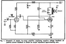
which has the diagram below which has negative voltage feedback and positive current feedback, to lower the output impedance to zero or make it negative.
I also note the 'snubbing' of the transformer to make it behave like a resistor.
That makes sense.
Found this link: http://www.aikenamps.com/zeroz.pdf
which has the diagram below which has negative voltage feedback and positive current feedback, to lower the output impedance to zero or make it negative.
I also note the 'snubbing' of the transformer to make it behave like a resistor.
Attachments
If this is planned for a P-P output stage, there may be some use for current sensing to reduce crossover distortion. See TubeCad Dec 20 and 30th, 2006:
2nd to last schematic:
European Triode Festival and Crossover Notch Distortion and New OTL Design
Broskie presents some somewhat obtuse methods to transcribe this to tube circuitry. But all thats needed is a differential driver stage to take the difference in the cathode current feedbacks. The differential feedback has higher gain when in class A overlapped mode, and lower gain in class B. So can be taken advantage of to smooth the output stage gain during a class AB crossover. Not much help for lowering the output Z in general though.
Yeah, positive current feedback should lower the output Z, as long as you don't use too much and turn it into an oscillator (negative output Z). If you use two of them (P-P and differential) in positive feedback mode though, it will do the opposite for class AB crossover distortion.
Usually when I see current feedback, they are trying to get critical damping of the speaker, which is at a higher Zo than the usual neg. V fdbk gives.
Last edited:
Positive current feedback will increase the gain of the earlier stage and make the amount of the global negative feedback higher( which is placed on that stage in post's #5 scheme ) and then lower the output impedance of the amp , so the problem is if that stage can stand this higher gain or not . IMO we have to design an gain stage biased like an high mu stage but with lower amplification then this stage can stand the effect of the positive current feedback ( I hope you understand what I mean because English is not my best ) .
Last edited:
The effect is to cancel some of the internal feedback of the input triode, making it act more like a pentode. If one envisions the triode plate voltage influence on cathode current as plate to cathode transconductance, the a.c. plate voltage times gm(pk) is the feedback current reducing change at the cathode. We're just cancelling some of that current to raise gain.
The same thing is done between the phase splitter cathode and input cathode in the Dynaco ST-35.
The same thing is done between the phase splitter cathode and input cathode in the Dynaco ST-35.
...will it try to change the OPT/amp into a current drive machine which would sound rubbish?
This is fact.. ?
Or would it be myth instead ?
This is fact.. ?
Or would it be myth instead ?
It's No.3: A question from someone who doesn't know
")
The effect is to cancel some of the internal feedback of the input triode, making it act more like a pentode. If one envisions the triode plate voltage influence on cathode current as plate to cathode transconductance, the a.c. plate voltage times gm(pk) is the feedback current reducing change at the cathode. We're just cancelling some of that current to raise gain.
The same thing is done between the phase splitter cathode and input cathode in the Dynaco ST-35.
Am I right in thinking that the triode effectively has variable resistance (like a MOSFET, but the Pentode is more of a variable current device (both being voltage controlled))?
If so you are saying that the current feedback tends to make a circuit behave like a pentode because its output is more of a current output - like a variable CCS?
Would it make a difference that I am using pentodes to drive the primary that I want to derive the current feedback from - would this just linearise the pentode?
Thanks for all the replies BTW, this must be basic stuff for you all but I want to understand the mechanisms rather than just relying on stabs in the dark
It's No.3: A question from someone who doesn't know
This is not an answer to the topic.
Can you definitely show the high output impedance causes "rubbish sound" ?
The reality may not be that black and white only.
Here is something for you to study:
http://www.google.fi/url?q=http://www.essex.ac.uk/csee/research/audio_lab/malcolmspubdocs/J12%2520Distortion%2520reduction%2520MC%2520current%2520drive.pdf&sa=U&ei=jN5MT8DaHo-L4gTRxu3wAg&ved=0CA8QFjAA&usg=AFQjCNGjn1pdoHjPrgoRfYjIA6tSvAEXiQ
Here is something for you to study:
http://www.google.fi/url?q=http://www.essex.ac.uk/csee/research/audio_lab/malcolmspubdocs/J12%2520Distortion%2520reduction%2520MC%2520current%2520drive.pdf&sa=U&ei=jN5MT8DaHo-L4gTRxu3wAg&ved=0CA8QFjAA&usg=AFQjCNGjn1pdoHjPrgoRfYjIA6tSvAEXiQ
If you have studied that paper, then you will know that in section 3 he discusses the problems raised by current drive, such as the bass peak I mentioned. Solutions are possible, but they do mean different speakers with either much higher mechanical damping or some form of motional feedback. So the paper simply repeats what I said, but in much greater detail. Thank you for agreeing with me.
This is not an answer to the topic.
Can you definitely show the high output impedance causes "rubbish sound" ?
Err.. I'm the original poster asking the question, sorry.
If I knew the answer I wouldn't need to ask....
On this picture feedback by current is positive, while feedback by voltage is negative. The result may be from low output resistance to even negative, depending on pot position. It is opposite to current drive.

Wavebourn, is the current feedback from the 200R pot at the right/bottom pot (Rk2 perhaps but it's a bit fuzzy)?
I'm guessing the voltage nfb is from Rf1 (60k)..
I.e. as the 6V6 conducts it pulls the centre of the 200R pot upward (current sense) and the anode pulls downward (voltage of anode vs centre point of 200R pot).
It's interesting because at no time does the voltage feedback actually reference the voltage of the primary, just of (B+ - primary voltage - a bit of Rk2) which means PSU ripples etc will not get corrected?
I wonder if there would be a benefit to drive the OPT with a cathode follower and ground the centre tap so the cathode feeds back the actual primary voltage? What do you think - has anyone done this?
Found a few tubecad articles on cathode follower outputs, like this one:
Cathode-follower power amplifiers
The main issue seems to be providing heater windings (one per output tube) and a driver circuit that goes negative enough to provide a sane idle current.
Perhaps a smarter move would be to use the aikido trick to feedback the power rail to compensate for the fact it's not a big feature of the usual anode feedback.
- Status
- This old topic is closed. If you want to reopen this topic, contact a moderator using the "Report Post" button.
- Home
- Amplifiers
- Tubes / Valves
- Primary current feedback - any good? Help!