Hi all,
A question for you gurus out there. I've 2 amps here where I've substituted the normal cathode resistor on the input valve for a red LED (~1.8v). It seems the LED can "clean" up the sound a bit, make it a little more precise.
So I'd like to ask.... why do I see red LEDs mentioned everywhere. Why not yellow, or blue or green? Are some inherently more noisy or something? Is htere ever a case where the resistor sounds better than the LED - fancy types?
Fran
Voltage and AC resistance, especially the latter. If you look at voltage divided by impedance as a figure-of-merit, reds score best (typical Vf of 1.7V, typical Z of 4-5 ohms). If a lower voltage is required, IR LEDs are nearly as good. There's a table in Morgan Jones's book giving the impedances and Vf for a variety of diode types.
I use red, green and IR leds in some of my designs, often works well even without a CCS on top. (In that case though you might want to select the tube for the plate current you want.) I find them a lot better sounding than any electrolytic bypass cap I have been able to find..
My preference is grid bias where it does not overly complicate the signal path.
My preference is grid bias where it does not overly complicate the signal path.
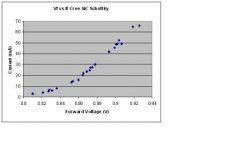
No need to limit the discussion to LEDs, either. The Cree SiC Schottky diodes have a Vf of 0.8-0.9 at typical valve currents, with low dynamic impedance. Here is a plot of the If vs Vf for the 400V version of the Crees.
This is a good tip, I've used 1N4148 and various small schottky types as well. I've found the garden variety 1N400x series not to be good sounding in this application probably due to some issue with dynamic impedance varying with signal current.
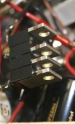
Thanks. I use them in my 2C22 preamp (see pic). They can be stacked neatly together to form a small package; that stack gives 3.4V bias at 15mA.
Note: There is no significance to the fact that one diode is stacked opposite the others - I started with the two face to face then added two others to the back as I experimented with different bias levels.
Note: There is no significance to the fact that one diode is stacked opposite the others - I started with the two face to face then added two others to the back as I experimented with different bias levels.
Attachments
I've read that the 1N4007 in particular can exhibit negative resistance characteristics similar to a tunnel diode.
This may help explain it's nasty noise generation as a HV rectifier unless a snubber, ferrite or both are used.
I would expect it to be a poor choice in a cathode circuit.
This may help explain it's nasty noise generation as a HV rectifier unless a snubber, ferrite or both are used.
I would expect it to be a poor choice in a cathode circuit.
A silicon diode that is forward biased really only has resistance and capacitance parasitics - both of which are non-linear but monotonic - I'd be absolutely amazed if any negative resistance character was exhibited in foward biased mode. As such, I think the diode differences are limited to those particular parasitics.
Maybe the quirky response is more about when they transition in to reverse withstand and exhibit reverse recovery.
Maybe the quirky response is more about when they transition in to reverse withstand and exhibit reverse recovery.
Rectifier diodes like 1N4007 can act like PIN diodes, but not as good as diodes designed for this and irrelevant to audio anyway. I have not heard of them acting like negative resistance diodes, but with a big central region (to get the voltage rating) I suppose something unexpected could happen.
- Status
- This old topic is closed. If you want to reopen this topic, contact a moderator using the "Report Post" button.
- Home
- Amplifiers
- Tubes / Valves
- LEDs on input valve cathodes