I got most of the parts on hand for my aikido octal headphone amp now. Figured i should setup my project thread.
Decided to go with solid state rectification instead of tube.
shoud be a nice compact amp =)
using NOS matched quad black plate RCA 6SN7-GTB's and the aikido is configured more like a line amp then a 'headphone amp' as per the designers suggestion for high impedance headphones on 6SN7
My only question/decisions to make now is chassis choice and should i do AC or DC on filaments? I know i need to take the filter cap off if i run AC
Transformer is rated at 50VA and has two 2 amp 6.3v windings, and a secondary winding with a 220 and 240v tap.
My coupling capacitors for the output are 80 uF 330v AC rated metalized film polypropylene by ASC
Considering using FRED bridge configured 1n4004~1n4007's for my b+
If DC is suggested, any suggested ways to go about it with 6.3v windings? seems like standard voltage regulator route would need rather low dropout voltage regulators
Decided to go with solid state rectification instead of tube.
An externally hosted image should be here but it was not working when we last tested it.
An externally hosted image should be here but it was not working when we last tested it.
An externally hosted image should be here but it was not working when we last tested it.
shoud be a nice compact amp =)
using NOS matched quad black plate RCA 6SN7-GTB's and the aikido is configured more like a line amp then a 'headphone amp' as per the designers suggestion for high impedance headphones on 6SN7
My only question/decisions to make now is chassis choice and should i do AC or DC on filaments? I know i need to take the filter cap off if i run AC
Transformer is rated at 50VA and has two 2 amp 6.3v windings, and a secondary winding with a 220 and 240v tap.
My coupling capacitors for the output are 80 uF 330v AC rated metalized film polypropylene by ASC
Considering using FRED bridge configured 1n4004~1n4007's for my b+
If DC is suggested, any suggested ways to go about it with 6.3v windings? seems like standard voltage regulator route would need rather low dropout voltage regulators
Last edited:
Hey.
6SN7s are some of the best triodes out there, it's perfect as a voltage amplifier, but it can't really pull a lot of current needed for an OTL headphone output. The output impedance would be too high.
I hope your PCB is configured with a White cathode follower output; if it's the Aikido output, forget about using it with headphones! And even if it's White CF, I also hope your headphones are *at least* 300 ohm...
And for a maximum efficiency White CF, the sensing resistor *has* to be calculated as it depends on the headphone impedance and the tube's internal resistance at the working voltage (it's not the value in the data sheet! it varies with voltage, it has to be also calculated/measured from the plate curves). Broskie and Cavalli have published articles discussing this matter.
If you have the place and a big heatsink, go for regulated DC. Use the 6.3v windings *in series*; it's the only way. You can't regulate 6.3vAC to get 6.3vDC. So in series you would get 12.6v DC at maximum 1.2A. (a 2A AC rated winding can only supply about 1.25A of DC current without overheating!!)
1.2A is exactly what you need for your 4 6SN7 in series + parallel on 12.6v. Use Schottky rectifiers (like the SB360) for your regulated heater supply - they have lower dropout and noise.
Forget about the 1N4007, use fast switching/soft recovery diodes instead...
im using the component/circuit design john suggested for 300 ohm headphones, he seems to somewhat suggest the 6SN7 in his manual
http://www.tubecad.com/Product_PDFs/Octal_Stereo_Rev_C.pdf look at bottom of page 8, and the component choices in page 9
i have a 12.6v SMPS i used in a older project i might re-use if its a bad idea to try and use the heater windings.
Following the trends in his chart at the end of the manual, i would expect 300~400 ohm output impedance which doesnt seem so bad
Guess ill quickly find out then if headphone amp was a terrible idea for the pcb. My friend got me the pcb as a gift and i dont have a need for a line amp so i figured i'd do headphone instead
Last edited:
I was saying that you can use your transformer for DC filaments - use the two 6.3vAC windings in series, that will give you 12.6vAC 2A; rectify and regulate (with a LM317) to 12.6vDC, and connect two 6SN7 filaments in series paralleled by the other two in series. ")
Use Schottky rectifiers (lower forward voltage drop, better quality). You should elevate your filaments too, as the upper triodes' cathodes will be about 120v above ground. (the 6SN7 can take up to 200v heater-cathode, but it may live longer and happier if you elevate the heaters).
Good luck!
Use Schottky rectifiers (lower forward voltage drop, better quality). You should elevate your filaments too, as the upper triodes' cathodes will be about 120v above ground. (the 6SN7 can take up to 200v heater-cathode, but it may live longer and happier if you elevate the heaters).
Good luck!
Last edited:
Member
Joined 2009
Paid Member
I'm also a bit nervous about the prospect of driving 300R from a 6SN7 cathode follower. The output impedance of a simple 6SN7 CF is around 300 to 400 Ohms if I remember right and Broskie wants it biassed at 14mA - a 1V swing into 300R is going to pull 20% of the idle current already.
I looked at the Aikido documentation you linked and it simply refers to 'high impedance'.
It's worth a try with the 6SN7's but it might be instructive to try something beefier to see what kind of difference you notice - just make sure your heater supply is flexible enough to give you some options.
I looked at the Aikido documentation you linked and it simply refers to 'high impedance'.
It's worth a try with the 6SN7's but it might be instructive to try something beefier to see what kind of difference you notice - just make sure your heater supply is flexible enough to give you some options.
Look at the last paragraph on page 9, he specifically mentions 300 ohms. but im willing to give it a try. The only issue is it might be 'Weak' driving the headphones right?
perhaps i was mislead ill find out when i wire it up i supposeOn the other hand, if only 300-ohm headphones are going to be driven,
then the best choice might be to use a 6SN7/12SN7 and both cathode resistors, R8 and
R11, leaving both resistors unbypassed. The output impedance will be higher, but the
distortion will be lower.
Last edited:
By all means, build it! It may sound good, even if the bass is too loose because of the high impedance.
Try it with and without the cathode bypassing capacitor (use a high quality one, like the Elna Silmic II).
You can even set it up as an optimized White CF to halve the output impedance if you are not satisfied with the Aikido configuration! (Broskie reported that he built one with 6SN7s in White CF output and said it sounded good...)
I see some good russian PIO's on the board!
It may sound good, even if the bass is too loose because of the high impedance. Try it with and without the cathode bypassing capacitor (use a high quality one, like the Elna Silmic II).
You can even set it up as an optimized White CF to halve the output impedance if you are not satisfied with the Aikido configuration! (Broskie reported that he built one with 6SN7s in White CF output and said it sounded good...)
I see some good russian PIO's on the board!
I have to choose a chassis and purchase some misc parts. I think im going to try AC on the heaters as there indirectly heated anyways.
Im a big fan of the russian PIO's. im giving the russian polymer's a try tho(as you see on the pcb too, going to use a switch to switch between the two to give it a good compare)
I got a huge stash of 0.22 uF 1000v, 6 0.46 630v, 6~8 0.1 uF 1000v, and 12 or so 0.022 1000v K40y-9's. got the same capacitance range with the russian polymer caps too =)
got a box full of 1uF 1000v, and 4uf 630v, and two 10uf 630v PIO's. The interesting thing about them from experimenting is, one 10 uF PIO filtered my big 5 channel amp's first filter after the rectifier better then a 47 uF electrolytic, them both wired in parallel and i had absolutely zero hum. (i use 10 henry inductor and 188 uF final filter)
The Bass response sound be fine from a coupling pov, i went extremely overboard at 80 uF, its a matter of what the tube/circuit can handle.
I could increase the idle current which would reduce output impedance(from my understanding)as i think the GTA/GTB were designed to be treated rougher then the classic 6SN7? or was that plate voltage only.
Last edited:
Yeah, maybe weak drive, less control on the headphone = looser bass (which you may like, who knows..) and distortion at high volume, I guess. Try it!
Broskie says "the best choice *might be* to use .. both resistors". Then again, Broskie says a lot of stuff that he only imagined but never tried...
Broskie says "the best choice *might be* to use .. both resistors". Then again, Broskie says a lot of stuff that he only imagined but never tried...
plugging my headphones directly into my phone/laptops outputs which are horribly suited for driving them (100% volume and still quiet) the bass response is fine, so i have my hopes up for desirable performance. Ill update you guys when i get it all put together. maybe ill get the misc parts and wire it up on the table to have a listen.
If i were to play with anything in the circuit, hotter bias, and maybe try the white cathode follower configuration? My only deviation from Broskie btw is i planned for 300v b+ so 150v per half. and following his chart for 300v the output impedance using linear interpolation plants the Zo right at about 300~350 ohms
I wont have my new oscilloscope for a while tho, i sent my old one to my friend. analysis will have to be done at a much later date
oh the headphones are rated at 97 dB per millivolt so i dont think i need anywhere near 1v swing unless i want my ears to bleed
Last edited:
Member
Joined 2009
Paid Member
I could increase the idle current which would reduce output impedance(from my understanding)as i think the GTA/GTB were designed to be treated rougher then the classic 6SN7? or was that plate voltage only.
The output impedance is related to the transconductance of the tube. It's true that the transconductance can be a function of the bias current. But looking at the curves you'd have to increase the idle current by 30% for a 10% reduction in output impedance. Since the max rating is around 20mA you don't have much room there - probably not worth shortening the tube life.
Looking at the plate curves in the datasheet, I would say that you can't go higher than 16mA at 150v. At that op point the grid bias would be about 1 volt; Biasing even hotter would get you too close to grid current even with new and strong tubes and more so with used ones (and real tubes may not exactly match the datasheet curves, you will have to measure your cathode voltage to see where your bias point settles).
What headphones are we talking about?
What headphones are we talking about?
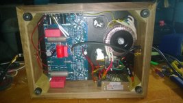
been a while since i have given any updates on this project.
i replaced the transducers in my headphones with 600 ohm ones(old ones broke when nephew dropped the headphones), the aikido amp can run sounds as low as 40 hz through them going by tone tests. using 4 6sn7's and recommended idle current for low distortion with high impedance headphones.
It has enough power to have to turn volume down to around 40% to keep my ears from hurting
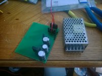
the little box is a line filter(power from the house is terrible)
regulated bplus runs at ~295v
also replaced the motor run caps with 15 uF mkp4 wima capacitors. lower value to reflect higher impedance headphones.. they sound incredibly better then the 80uF motor runs
i replaced the transducers in my headphones with 600 ohm ones(old ones broke when nephew dropped the headphones), the aikido amp can run sounds as low as 40 hz through them going by tone tests. using 4 6sn7's and recommended idle current for low distortion with high impedance headphones.
It has enough power to have to turn volume down to around 40% to keep my ears from hurting
the little box is a line filter(power from the house is terrible)
regulated bplus runs at ~295v
also replaced the motor run caps with 15 uF mkp4 wima capacitors. lower value to reflect higher impedance headphones.. they sound incredibly better then the 80uF motor runs
Attachments
Last edited:
- Status
- This old topic is closed. If you want to reopen this topic, contact a moderator using the "Report Post" button.
- Home
- Amplifiers
- Tubes / Valves
- Aikido Octal Headphone amp