SansyG, I may be wrong in your particular case, but I had similar issue with similar amplifier. The real culprit was output transformer. Probably it had some arching between adjacent turns of winding (enamel coating is defect or scratched).
After I replaced transformer, everything went OK.
Do you have 2nd output transformer?
After I replaced transformer, everything went OK.
Do you have 2nd output transformer?
How is lead dress in the area of the first stage - nice tight short leads? Try adding a 1K resistor between pin 7 and the 0.47uF capacitor, right at pin 7. I think you'll probably find this kills the oscillation.
You mean V6B 12BH7A grid and C16? Kevin, what is purpose of this resistor?
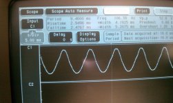
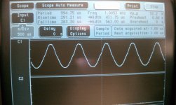
Ok, tried a 200pf cap across C15, did nothing.
Tried the 9.4Meg resistor across C15 (Pin 7 to ground). Signal is pretty clean. So something clear that is odd with the input stage.
I wonder if R20 at 1Meg is too high a value, but I really don't know the theory on how this circuit works.
Kevin - The leads and other parts are pretty close on the circuit board, but could be something like that. And for your test was that to place the 1K resistor before Pin 7 and the 1M and 0.47uf cap?
LinuksGuru - Don't think it's an output transformer as the signal is clean when I play a bit with the input circuit as mentioned. The output transformer is new, and I think I would see some odd intermittent signals (and hear it for sure).
Sandy
Attachments
You mean V6B 12BH7A grid and C16? Kevin, what is purpose of this resistor?
No C15, on V5B Pin 7
Sandy
No, I think he means on the first stage. I was going to suggest this, but kevinkr beat me to it. It could well be that the original caps were sufficiently lossy at RF that they didn't need stoppers.
As a general rule, if a circuit is behaving strangely and touching it stops it or changes the behaviour then there is a good chance the stage you touched is oscillating at RF.
PS putting a resistor to ground will changes the bias of the top triode and probably reduce its gain, so killing the oscillation. It might also reduce the gain of the bottom half, so that could be the culprit too.
Last edited:
<snip>
Kevin - The leads and other parts are pretty close on the circuit board, but could be something like that. And for your test was that to place the 1K resistor before Pin 7 and the 1M and 0.47uf cap?
<snip>
Yes, just lift the connections at pin 7 and solder a 1K resistor from pin 7 to the lifted connections. (1M and 0.47uF cap) - this can be a permanent fix if it works. Since this is a pcb perhaps you can just cut the etch near pin 7.
Note that the 1M resistor provides grid leak bias for the upper triode in the cascode so there may not be a huge amount of room for tinkering with the value.
Sandy[/QUOTE]
I wonder if the old time paper capacitor that was used in the 50's was loss-y enough resistance wise to keep things stable?
Hey toss the new kid a bone
") Well I guess if I keep guessing I would have got the right answer eventually!
Well I guess if I keep guessing I would have got the right answer eventually!I'll give that a shot, might have to hack up a bit to try it, nothing a dremel and small drill can't fix!
Back to the lab... well the garage and take it apart again.
PS putting a resistor to ground will changes the bias of the top triode and probably reduce its gain, so killing the oscillation. It might also reduce the gain of the bottom half, so that could be the culprit too.
The output clipped a bit earlier with the 9.4Meg resistor across the C15. The RMS voltmeter showed about 1 volt lower before clipping without the resistor.
This could also be the voltmeter getting a cleaner waveform that is causing a lower reading but hard to say.
Sandy
Back from the Lab
Adding in the 1k resistor before Pin 7 of the 12AU7A had no effect that I can see. Signal was bad at 100Hz and 1kHz as in the original with the odd oscillations.
Sandy
Time to post a picture of the board layout showing how things are placed, and your grounding scheme.. (How long and how heavy is the ground trace to the 0.47uF cap?)
Probably time to start thinking about a more conventional cascode design as well. Did the original design use a shield over the tube?
Also what about R7? Using the 100K specified or something less?
Kevin -
Did you mean R17 on the input of the 12AU7? That is left at 100K
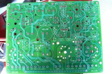
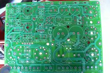
I will have to get a better picture but here is a camera phone image.
The board is made with 2 Oz copper and has generally very wide traces for all connections.
The ground system is sort'a split into 2 regions with fairly heavy traces for all.
Here is a top and bottom view, but I'll have to find the digital camera for a higher res shot.
Also I don't think they had a shield on any tubes on the original 260A from what I saw.
Sandy
Did you mean R17 on the input of the 12AU7? That is left at 100K
I will have to get a better picture but here is a camera phone image.
The board is made with 2 Oz copper and has generally very wide traces for all connections.
The ground system is sort'a split into 2 regions with fairly heavy traces for all.
Here is a top and bottom view, but I'll have to find the digital camera for a higher res shot.
Also I don't think they had a shield on any tubes on the original 260A from what I saw.
Sandy
Attachments
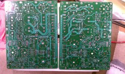
R17 may be too far away from the grid to act as a reliable stopper. Also the connection to this runs parallel to the cathode trace so there is scope for coupling at VHF/UHF frequencies. Your ground traces seem quite long and thin. Remember, the valve does not know you only intend it to amplify audio; it might think you are making an RF oscillator with resonant lines.
R17 may be too far away from the grid to act as a reliable stopper. Also the connection to this runs parallel to the cathode trace so there is scope for coupling at VHF/UHF frequencies. Your ground traces seem quite long and thin. Remember, the valve does not know you only intend it to amplify audio; it might think you are making an RF oscillator with resonant lines.
I am going to try to pull that and jump it from the pin of the tube. I might try to pull a wired ground lead right up to the input and see if that shoes anything different. I don't think it's a ground issue, but more a coupling issue. R17 makes sense and it does pass through the socket.
Thanks for taking a look, I'll give that a try, the one bad thing is that the trace from R17 is under the socket, will have to cut and pull to remove the trace.
Also remember that the thickness of the copper on this PCB is typically 2x as thick as what is normally used for production. Think of the traces as 2x as thick as they look
Sandy
Input stage is a cascode. The unusual thing is that the upper triode is run with almost zero grid bias, so it will drop very little anode-cathode voltage. This could give more headroom, but the downside is that the upper triode bias could vary with signal envelope.
Thicker copper will reduce resistance, but make little difference to inductance (which depends mainly on the biggest dimension - in this case track width).
My guess is that the stage is only just oscillating, so might not be too difficult to tame. I say this because reducing the lower anode voltage a little (by resistive loading of the upper grid) seems to cure it.
DF96 - I'll move some things around and see what it does. I don't have a feel for how sensitive tubes are to the parts placement, but getting a lesson now it seems.
I did the layout and PCB and built it. It is based on the Grommes Precision 260A which a few folks also have built here with very good results. Not sure if anyone besides me tossed theirs on a scope as I did (I would hope so). Also I think at least one or both of the other builds did their own PCB's as well.
I also just got a Sams Photo facts on the Grommes 260A and one thing it does have is voltages and confirmation of the original schematic I used. I don't have this handy at work but as I recall the voltage on the second grid of the 12AU7 was in the 35V range, but will have to recheck as I'm not 100%.
Sandy
Last edited:
Input stage is a cascode. The unusual thing is that the upper triode is run with almost zero grid bias, so it will drop very little anode-cathode voltage. This could give more headroom, but the downside is that the upper triode bias could vary with signal envelope.
Thicker copper will reduce resistance, but make little difference to inductance (which depends mainly on the biggest dimension - in this case track width).
My guess is that the stage is only just oscillating, so might not be too difficult to tame. I say this because reducing the lower anode voltage a little (by resistive loading of the upper grid) seems to cure it.
Grid leak bias, and the 12AU7A does draw appreciable grid current so there is likely a couple of volts effectively of grid bias there (any meter connected to the grid will significantly shift the operating point unless its dc input resistance is extremely high) - still not a great implementation as the bias can wander all over the place as a function of tube to tube variation. This sort of approach is sometimes used in phono stages, the desire being to maximize the cascode gain, more rarely seen in the front end of power amplifiers where unpredictable headroom seems somewhat likely.
Lowering the overall plate voltage slightly to this stage may help, other odd things to consider are decoupling the filaments of this tube to ground using small ceramic caps, and elevating the filaments so that the filament circuit is biased slightly above the cathode voltage of the upper tube in the cascode. (All this since the mechanism is not understood)
- Status
- This old topic is closed. If you want to reopen this topic, contact a moderator using the "Report Post" button.
- Home
- Amplifiers
- Tubes / Valves
- Need Help with New Amp Build, Ugly signals