Just finished up building one of the EZ260A amps which is based on the Grommes 260A. It sounds very good and only on a whim did I decide to put it on the scope to see what kind of power and how clean its signal looked.
It looked bad!
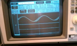
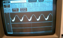
The 1Khz sine wave looked like it had some oscillations in it, and at 100hz more visible.
Not sure where to start working on this as this is my first tube project. I'm waiting for another set of tubes to see if potentially I have a bad one, but not sure if the waveforms will give a clue to help get me messing with it.
One other thing I did note when bringing it up on the Variac was that without a load the amp seems to motorboat. With an 8 ohm dummy load, stable. With a speaker, stable and no noise while idle.
Any ideas where to start looking for the problem. (scope pics and schematics attached)
Thanks
Sandy
It looked bad!
The 1Khz sine wave looked like it had some oscillations in it, and at 100hz more visible.
Not sure where to start working on this as this is my first tube project. I'm waiting for another set of tubes to see if potentially I have a bad one, but not sure if the waveforms will give a clue to help get me messing with it.
One other thing I did note when bringing it up on the Variac was that without a load the amp seems to motorboat. With an 8 ohm dummy load, stable. With a speaker, stable and no noise while idle.
Any ideas where to start looking for the problem. (scope pics and schematics attached)
Thanks
Sandy
Attachments
The box with the RC you have labeled "Optional" isn't - it's the amplifier's lag compensation network for HF stability. You may fiddle with the values to optimize square wave response. (Minimal overshoot and ringing on edges without killing the HF response totally. A 1kHz square wave is usually suitable for doing this, then check at 10kHz to see what sort of performance you get.)
Also C14 may be applicable in certain cases, but depending on the output transformer used it may be better left out. First add the lag compensation and then recheck with C14 in and out of circuit.
Also C14 may be applicable in certain cases, but depending on the output transformer used it may be better left out. First add the lag compensation and then recheck with C14 in and out of circuit.
Thanks Kevin,
The optional box comment should have been removed. I started with a 250pf cap in C17 and upped it to 500pf and it help clean things up a bit, but still the ugly wave forms persisted. In some documents I found they had a 250pf, other had 470pf, so was unsure what the value was. Seems 470/500pf is what was used.
Thanks on the tip (both Kevinkr/Mississippi) on the feedback, I'll remove C14 and see what the waveform looks like.
Also, the output transformer is an 100watt Edcor with 4200 ohm plate. I am not using the ultra-linear taps, but using the fixed screen option leaving the UL taps un-connected.
Sandy
Hi Sandy,
Not sure why you aren't using the UL connections as running this amp in pentode connection definitely affects the overall output stage gain and phase margin, the UL connection provides local feedback between the screens and plates. The transformer design is probably optimized for UL operation as well, there being numerous tradeoffs between leakage inductance and interwinding capacitance to be made. In pentode connection leakage inductance is less of an issue than interwinding capacitance since the source impedance is high, in UL operation the feedback reduces the effective rp considerably and makes the output stage somewhat more sensitive to leakage inductance and less so to capacitance - the extreme case is triode connection where leakage inductance becomes a really big deal.
The above is grossly simplified but hopefully helps. I would strongly recommend the UL connection be tried.
I would disconnect the feedback loop and compensation and figure out the phase and amplitude response of the output transformer and see how the pentode connection and UL connection differ.
With the pentode connected output stage you may need to reduce the value of R22 slightly in addition to increasing the value of that cap.
Do you have screen stoppers? The oscillation could be taking place in the output stage rather than the feedback loop. Temporarily disconnecting or reducing the feedback would show this.
Somewhat strange circuit. R23 appears to have no function, unless it is a warning of marginal output stage stability. The upper 12AU7 has strange bias arrangements, relying on grid current - OK for small signal inputs but could get bias shift with larger signals. The 12BH7 has too low mu for a LTP phase splitter without a CCS tail, so it needs manual adjustment for balance.
Somewhat strange circuit. R23 appears to have no function, unless it is a warning of marginal output stage stability. The upper 12AU7 has strange bias arrangements, relying on grid current - OK for small signal inputs but could get bias shift with larger signals. The 12BH7 has too low mu for a LTP phase splitter without a CCS tail, so it needs manual adjustment for balance.
The 1Khz sine wave looked like it had some oscillations in it, and at 100hz more visible.
Not sure where to start working on this as this is my first tube project. I'm waiting for another set of tubes to see if potentially I have a bad one, but not sure if the waveforms will give a clue to help get me messing with it.
You've got snivets there. Your schemo doesn't include screen stoppers for the finals. It's a Barkhausen oscillation that's occurring at plate current cutoff. Never used KT88s myself, but I've seen the same thing with 807s. (Damped 60KHz oscillations when they hit plate current cutoff.) Adding 1K5 screen stoppers damped out the oscillation. (6BQ6s didn't show these snivets, but I included 680R screen stoppers just in case.)
One other thing I did note when bringing it up on the Variac was that without a load the amp seems to motorboat. With an 8 ohm dummy load, stable. With a speaker, stable and no noise while idle.
You're going to get problems like that with gNFB sometimes. Dropping the voltage with a Variac will reduce the open loop gain, and that, in turn, can cause instability.
Nyquist Criterion: "The number of unstable closed loop poles is equal to the number of open loop unstable poles plus the number of encirclements of the point: -1 + j0".
The denominator of the transfer characteristic is: D(s)= G(s)H(s), where G(s) is open loop gain, and H(s) the x-fer characteristic of the feedback network. Given that, reducing G(s) can sometimes cause the whole characteristic to hit that -1.0 + j0 point. Less open loop gain can make for instability.
 It's counter-intuitive, but it does happen, and some amps will have a burst of noise when you power off, cathodes cool, filter capacitors discharge, and open loop gain falls off. It's something you'd like to avoid if at all possible since that means a marginally stable design that might be put into full-blown oscillation if different speeks with different impedances are connected. It could also mean that you have rising gain over a narrow band of frequencies that could prove detrimental to sonic performance.
Do you have screen stoppers? The oscillation could be taking place in the output stage rather than the feedback loop. Temporarily disconnecting or reducing the feedback would show this.
Somewhat strange circuit. R23 appears to have no function, unless it is a warning of marginal output stage stability. The upper 12AU7 has strange bias arrangements, relying on grid current - OK for small signal inputs but could get bias shift with larger signals. The 12BH7 has too low mu for a LTP phase splitter without a CCS tail, so it needs manual adjustment for balance.
I will toss the scope on the driver stages to see what it looks like. The original circuit is pretty close to what I have except for the missing internal impedance adjustment which Grommes removed back in the day.
After looking at the driver stages it's seemed more unconventional then some of the other drivers for KT88's (I have Triode Electronic in my Dynaco MK3's).
R23 Was a reminant of the old grommes internal impedance circuit and was left in. I had it in and also removed it with no difference in open load stability. I left the ability to stuff the PCB with it as my Dynaco MK3's have a 680ohm across the 16ohm/feedback output tap which I'm guessing is a stability fix, which is fine if it works. I'll work on the motorboating issue later as I think it may be un-related to the fedback issue, which might be the first issue.
[edit]
One last thing is that I used 10ohm 2 watt resistors on the cathodes of the tubes to measure the bias.
Last edited:
Miles - Go easy on the theory, I'm just starting out
Sorry if I wasn't clear. I did bring up the power full on the Variac and on its watt meter you could see the power draw jump around a bit, so as I suspected it was motor boating without a load (And confirmed when tossed it on the scope)
I can easily try the screen resistors since in the PCB I have a jumper that can be cut.
And to learn as I go do the screen stopper prevent oscillation or just prevent a problem during an overload situation? The Screens are driven by the 6L6GC although both tied together, not sure how that might impact things, But will try a 1K5 in each of the screens to see what it does. My guess is that it might only help with the motor boating issue without a load and a safety net if over driven. (all newbie speculation of course)
I don't think the amp is that far off, it was an odd choice to base one on, but I had seen a few people comment on how good they sounded so figure hey, lets try something odd.
And I can say that I spent an afternoon listening to every type of music I had and with it and the modded Dyanco MKIII used for the other channel sounded very good. So I think with a bit of clean up on some parts values it will come out sounding very well (I might be too easy to please...) .
Attached is the original Grommes 260A for reference as well.
Attachments
Don't run a valve amp without a load, unless you have lots of money to keep buying new OPTs. Screen stoppers prevent the output valves from oscillating at RF.
If you scope the driver stage you may still see the oscillation, as it will come round the feedback loop. Perhaps attenuated by the compensation network, though. Remove or reduce the feedback. If that stops the oscillation then you have a loop stability issue. If it doesn't stop it, then you probably have output stage parasitic oscillation. Different problems, different cures.
If you scope the driver stage you may still see the oscillation, as it will come round the feedback loop. Perhaps attenuated by the compensation network, though. Remove or reduce the feedback. If that stops the oscillation then you have a loop stability issue. If it doesn't stop it, then you probably have output stage parasitic oscillation. Different problems, different cures.
Don't run a valve amp without a load, unless you have lots of money to keep buying new OPTs. Screen stoppers prevent the output valves from oscillating at RF.
I am guessing you mean when it is driven? With the input shorted and with a stable circuit I would expect this not to be a problem, but I'm learning as I go!
I'll be hitting the bench with the Amp this weekend and will try the feedback suggestions first, then the screen stoppers to see what affects the problem.
Huge thanks for all the suggestions, doesn't feel that bad now with some ideas to try.
Sandy
Thanks DF96. Hopefully will get some time this weekend to play with the changes.
For those that have not seen the build thread, here's the link.
http://www.diyaudio.com/forums/tubes-valves/194337-ez260a-grommes-260a-project-2.html
Sandy
For those that have not seen the build thread, here's the link.
http://www.diyaudio.com/forums/tubes-valves/194337-ez260a-grommes-260a-project-2.html
Sandy
A stable amp may be OK with no input and no load, but you would need to ensure no operator error!
Other than the fact that a tube amplifier is calculated based on the OT load, there is no problem. The load is part of the circuit.
Got a few minutes to play with some changes on the amp -
1. Pulled the Feedback off the transformer and the amp became unstable at idle (No signal). With some signal it calmed down.
2. Changed the Feedback resistor for 27k to 10k (arbitrary value) and it did not seem to make much difference except on the required drive. Both the 100Hz and 1kHz signals looked as original.
I did not get a chance to pull the board and cut the screen traces to install the screen stoppers, but will try that as soon as I can.
Sandy
Got a few minutes to play with some changes on the amp -
1. Pulled the Feedback off the transformer and the amp became unstable at idle (No signal). With some signal it calmed down.
<snip>
Sandy
That indicates that there is a really serious stability issue with your design or layout. Make sure the secondary is loaded when you do your testing, but you need to identify the source. Screen stoppers may help, there may also be some issues with the board layout that make the design marginally unstable.
Be methodical and verify that each stage in succession is not at the root of the problem starting at the input and working your way to the output - unless you are absolutely certain the output stage is oscillating as it may not be.
Check that input stage with the input shorted and unshorted, maybe even plugged into an interconnect that is not connected to anything at the other end - you should see no misbehavior other than some minor hum pick up...
Check that the supplies are adequately decoupled at all frequencies..
Etc.. Others will have a lot to add I'm sure..
Thanks Kevin,
I think the first step will be to add the screen stoppers and see if that helps or changes anything.
How critical are the values for the stoppers, I think DF96 recommended to try 1.5k which I have so will give it a shot.
Then do the recheck of component values, could be something as simple as a wrong stuffed part, but that would be too easy a fix
Sandy
DF96 -
I tried it both ways, when I had the 10k in series with the existing 27K it didn't make much difference to the ugly signal other then sensitivity. So effectivly had 10k in one test, 27k stock initial value, and 37k for feedback.
I will try 1K in the Screens as soon as I can take the board off the chassis.
And all testing was into an 8ohm dummy load, some with a shorting plug and some with just the cable.
I will start to write this stuff down as it is not very accurate of me to try to remember all the test cases.
Hopefully the screen stoppers will clean things up.
Sandy
Did a bit more testing today on the amp. Added 1K screen stoppers to the amp, and didn't see too much different on the 100Hz signal or the 1kHz. I did not try to run the amp without a load to see if it was stable.
Now I decided to look at the driver stage, in the 12AU7A slot I tried a 6189 and 5814 to see if it was a tube issue, but no difference was noticed. I left the GE 5814 in moving forward.
So I started looking at C15 and the 0.47uf cap as a suspect, and while observing the scope as the amp was showing it's odd ringing pattern on part of the waveform, I was probing voltages and as soon as I hit the Pin 7 of the 12AU7A the signal was perfectly clean!
I was probing with a Fluke 189 meter (volts mode) and I'm not sure why but the signal is perfect with the probe on Pin 7 of the tube, but I did a sweep and it looked very good, removed probe, back to unstable.
So it seems the ringing is in the first stage of the amp.
I think DF96 mentioned that it was odd the way it was biased (self) but not exactly sure.
I the Fluke meter specs show a 10meg impedance with 100pf on the voltage measurement inputs so could be a combination of both that cleans up the circuit, but not sure. I'm going to make a tester with 2-4.7M resistors in series and see if that has the similar effect as when the probe is on Pin 7, another words I'll do a 9.4M resistor from Pin 7 to Ground and see if that cleans things up.
Also for C15 I was using a Solen .47uf 630v cap, I swapped it for a low cost Xicon Polyester (I think) cap and noticed a slightly worse ringing.
I wonder if the old time paper capacitor that was used in the 50's was loss-y enough resistance wise to keep things stable?
Ok, I'm going to try the resistors and see what give, but any thoughts always welcome!!
Sandy
P.S. No, I don't want to listed to the stereo with my Fluke Multi-Meter Connected no matter how good it cleans up the signal
- Status
- This old topic is closed. If you want to reopen this topic, contact a moderator using the "Report Post" button.
- Home
- Amplifiers
- Tubes / Valves
- Need Help with New Amp Build, Ugly signals