Wow, one more perforated chassis! Good choice!")
I actually built it first with a solid plate and rethought how much heat I would be producing inside the chassis. I decided to re-do it correctly instead of spending all this time building something that may not end up being reliable.
What peak current did you think the zener would get to? Is your drive able to push the KT88 in to saturation, and hence get zener current perhaps above 50-100mA pk, or were you designing for down around 20mA ? It looks like a few series leaded zeners will have a working resistance of a few hundred ohms. The transient suppressor types (eg. BZW03) have good rated non-repetitive surge levels. Your regulator may also have a current limit, which would divide up during start-up.
Wrt the screen current characteristic, I would have though it would always be positive, and probably not get down below 1-2mA even at high anode voltage and low screen voltage levels. Although I guess leakage inductance effects could move the screen voltage down lower.
I'm restoring an AWA 100W PA amplifier (model PA1001). In Australia, AWA were a large company who made a lot of PA/industrial amps. I haven't got a schem up yet, but the screen-cathode cap was 2x 4u7 450V in series, with a 220k across each cap for voltage apportioning. That's quite a bit of effort to go to, but possibly a lot less effort than winding a McIntosh style OT !
My amp will more likely than not get used for guitar amp work, so I like the idea of a zener as I don't think my amps bootstrapped drive will push the 6L6's into saturation region, so it may be worth trying for a softer earlier compression by lowering the screen voltage. But I'm still trying to get my head around the subtleties of unity-coupled because I'm newb with this config, and the PA1001 and PA1002 amps are the only Australian amps I know of that use this config. I haven't been through all the McIntosh amp versions - do you know of any unity-coupled amps that used cathode-screen caps and bootstrapped drivers?
Ciao, Tim
Last edited:
I notice the Krone-Hite UF-101 uses 10uF screen-cathode bypass caps, but the instruction manual doesn't identify the detailed winding structure of the output transformer. Even the original patent points towards a benefit in using some capacitance for higher frequency operation.
A quick calc of the zener power loss, even when averaging is thrown in, is going to become fairly substantial. Maybe a FET based psuedo zener may be worth it, just for the ability to provide simple heatsinking of a fet - although I guess a few small-stud 50V zeners may suit, or just 5W zeners with copper disks as heatsinks at the junctions of the zeners.
A quick calc of the zener power loss, even when averaging is thrown in, is going to become fairly substantial. Maybe a FET based psuedo zener may be worth it, just for the ability to provide simple heatsinking of a fet - although I guess a few small-stud 50V zeners may suit, or just 5W zeners with copper disks as heatsinks at the junctions of the zeners.
What peak current did you think the zener would get to?Is your drive able to push the KT88 in to saturation, and hence get zener current perhaps above 50-100mA pk, or were you designing for down around 20mA ? It looks like a few series leaded zeners will have a working resistance of a few hundred ohms. The transient suppressor types (eg. BZW03) have good rated non-repetitive surge levels. Your regulator may also have a current limit, which would divide up during start-up.
I was mostly concerned about power-up surge. It looks like 8uF would give a surge that would peak at 1.2A and would be over in 4mSec. Is it safe to assume that my output transformer primary would be okay with that? I have no idea what gauge of wire it uses or whether this is a totally paranoid concern I have.
I have some 1N5378B's laying around and spent some time looking at the datasheet today. I think that the Diodes will be fine at power-up. I will have to look to see how they will handle continuous amp clipping. The driver will be capable of driving the power tubes to saturation so I need to make sure I won't blow these out.
Wrt the screen current characteristic, I would have though it would always be positive, and probably not get down below 1-2mA even at high anode voltage and low screen voltage levels. Although I guess leakage inductance effects could move the screen voltage down lower.
It will certainly never be negative(unless the screen is glowing) but should go to zero when the tube is cut off. No electrons through the tube will mean none for the screen to intercept.
I'm restoring an AWA 100W PA amplifier (model PA1001). In Australia, AWA were a large company who made a lot of PA/industrial amps. I haven't got a schem up yet, but the screen-cathode cap was 2x 4u7 450V in series, with a 220k across each cap for voltage apportioning. That's quite a bit of effort to go to, but possibly a lot less effort than winding a McIntosh style OT !
My amp will more likely than not get used for guitar amp work, so I like the idea of a zener as I don't think my amps bootstrapped drive will push the 6L6's into saturation region, so it may be worth trying for a softer earlier compression by lowering the screen voltage. But I'm still trying to get my head around the subtleties of unity-coupled because I'm newb with this config, and the PA1001 and PA1002 amps are the only Australian amps I know of that use this config. I haven't been through all the McIntosh amp versions - do you know of any unity-coupled amps that used cathode-screen caps and bootstrapped drivers?
That sounds like a cool project. Something you may want to look at if you haven't yet is the Crowhurst twin-coupled design. It uses two normal output transformers with coupling caps to simulate a bifilar winding arrangement.
I notice the Krone-Hite UF-101 uses 10uF screen-cathode bypass caps, but the instruction manual doesn't identify the detailed winding structure of the output transformer. Even the original patent points towards a benefit in using some capacitance for higher frequency operation.
A quick calc of the zener power loss, even when averaging is thrown in, is going to become fairly substantial. Maybe a FET based psuedo zener may be worth it, just for the ability to provide simple heatsinking of a fet - although I guess a few small-stud 50V zeners may suit, or just 5W zeners with copper disks as heatsinks at the junctions of the zeners.
I'm coming up with about 6W in the zener if the amp is continuously driven to clipping(using my load line and 6550s). There's no way a 5W zener is going to like that. However, the amp shouldn't see continuous clipping. Still, I don't want it to die if it does... I'll have to think about this a bit more.
I'd be thinking the peak screen current could get quite high if you can drive in to saturation - that could be a lot of peak repetitive power dissipation! Maybe a psuedo zener where regulation is lost above a certain current could keep the zener out of strife. (Eg. http://dalmura.com.au/projects/Selmer Organ Added Schematic1.gif was for a 300V zener - it's regulation is not super, but perhaps ok).
I reckon a primary winding that can cope with repetitive peak current in the hundreds of mA would be absolutely fine for a one off peak of 1.2A.
The 1N5378B is going to need substantial disk heatsinks soldered very close to the package to get anything close to 5W dissipation capability - especially under a chassis.
How about just a source follower driving the screen? That should be pretty low zout and it will be easy to heatsink. I've shown it with a zener but a resistive divider would be fine as well since the voltage between cathode and opposite plate stays constant.
I'm actually thinking I will use some sort of grid current limiting resistor(1k?) for the KT88 so that if the load line crosses above the knee of the curves(which it should with the lower screen voltage) it will stick there so as to not cause off-the-charts screen currents and be too hard on the mosfet.
I'm actually thinking I will use some sort of grid current limiting resistor(1k?) for the KT88 so that if the load line crosses above the knee of the curves(which it should with the lower screen voltage) it will stick there so as to not cause off-the-charts screen currents and be too hard on the mosfet.
Attachments
I definitely agree about the grid stopper if you can push in to grid conduction.
I was noting a comment re the Cathamplifier, and I think also in the Kron-Hite, about the benefit of the screen cathode bypass cap also constraining the varying screen current to just that loop, rather than a loop that also includes the ground-cathode winding, and hence introducing a distortion component which may well become significant if the loadline gets toward the knee region (eg. under non resistive loads, or for speaker resonance frequencies).
I was noting a comment re the Cathamplifier, and I think also in the Kron-Hite, about the benefit of the screen cathode bypass cap also constraining the varying screen current to just that loop, rather than a loop that also includes the ground-cathode winding, and hence introducing a distortion component which may well become significant if the loadline gets toward the knee region (eg. under non resistive loads, or for speaker resonance frequencies).
I designed and built an autobias board (around the "Broskie auto bias" curcuit, see this thread) for this amp. I have yet to wire it up and test it.
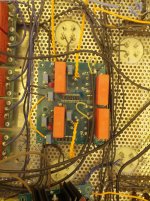
I also build a board for the output tubes that includes the source follower grid driver and mosfet-follower based screen regulator (since it needs four individual floating regulators for this amp). I implemented current limiting on the screen regulator since it was only an extra couple of resistors and a BJT. Now if I drive the tubes into saturation the screen voltage will just sag instead of making the screens glow.
I will be posting some pics and test results as they come.
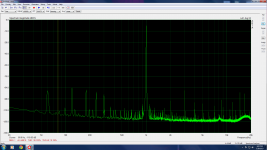
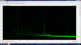
I finally got the input board for my amp installed and tested a bit. My sound card is kind of crappy. These measurements were taken at the output of one plate, they are not differential measurements.
I was surprised at how the 3rd harmonic was dominant. I expected 2nd to dominate. Are these good results for a first stage? I have no basis for comparison as this is my first amp.
Edit: First picture is 1Vrms in, 9Vrms out. Second is 2Vrms in, 18Vrms out. Third is ground for reference.
I was surprised at how the 3rd harmonic was dominant. I expected 2nd to dominate. Are these good results for a first stage? I have no basis for comparison as this is my first amp.
Edit: First picture is 1Vrms in, 9Vrms out. Second is 2Vrms in, 18Vrms out. Third is ground for reference.
Attachments

Last edited:
I would not worry about 3rd and 2nd harmonics at this level. They are so small and in a well made PP the even harmonics are going to cancel anyway.....
I would rather see the effect of those supply harmonics at the output as function of Pout. They can be small at low output (or at the input stage as in your case) but increase quickly as the Pout increases. This because the IMD harmonics are multipied by a term which increases with the power given by the harmonic itself (i.e. 2nd harmonic increases with the square of its "gain" coefficient, 3rd harmonic increases with the cube etc...). So a very small intermodulation product can become important (or even dominant) at higher output level. The IMD 3rd harmonic is usually the nasty one.
I would rather see the effect of those supply harmonics at the output as function of Pout. They can be small at low output (or at the input stage as in your case) but increase quickly as the Pout increases. This because the IMD harmonics are multipied by a term which increases with the power given by the harmonic itself (i.e. 2nd harmonic increases with the square of its "gain" coefficient, 3rd harmonic increases with the cube etc...). So a very small intermodulation product can become important (or even dominant) at higher output level. The IMD 3rd harmonic is usually the nasty one.
Thanks for the thoughts, 45. I realized that I had never measured the output of the cheap DVD player I am using as a generator. It seems like the majority of the higher order crap and a significant amount of the lower order stuff comes from the source...
Next I have to wire up the driver/CCS board for the 841s to see how well those perform. I need to develop 200Vrms there to drive this output stage so wish me luck. I'm hoping that the 841s do well.
Next I have to wire up the driver/CCS board for the 841s to see how well those perform. I need to develop 200Vrms there to drive this output stage so wish me luck. I'm hoping that the 841s do well.
Attachments

- Status
- This old topic is closed. If you want to reopen this topic, contact a moderator using the "Report Post" button.
- Home
- Amplifiers
- Tubes / Valves
- Unity-Coupled amp project