A triode with a constant current obeys the simple rule:
Vp = Mu x Vgk
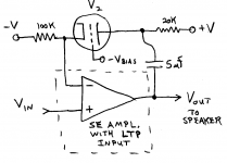
Usually one thinks of Vp as the output and Vgk as the input. But this can be reversed as well. By grounding the grid and applying signal to the plate (Vp), the cathode (Vgk) will have an (AC) voltage of Vp attenuated by Mu. Since the usual resistive feedback network for a P-P amplifier is an attenuator, one can replace it with the triode attenuator. See attached diagram:
The usual feedback loop operation controls the amplifier output so as to maintain nearly zero difference between the amplifier input signal and the attenuated feedback signal. So, Vgk will nearly equal the amplifier input signal, and since Vgk = Vp/Mu , Vp (or the amplifiers output) will be Vinput x Mu. This is what the ideal one tube SE amplifier would produce, but with the power of a P-P amplifier in this case. Anyone try this?
Variations on this idea are presented at this website:
http://www.ne.jp/asahi/evo/amp/el86/report.htm
Vp = Mu x Vgk
Usually one thinks of Vp as the output and Vgk as the input. But this can be reversed as well. By grounding the grid and applying signal to the plate (Vp), the cathode (Vgk) will have an (AC) voltage of Vp attenuated by Mu. Since the usual resistive feedback network for a P-P amplifier is an attenuator, one can replace it with the triode attenuator. See attached diagram:
The usual feedback loop operation controls the amplifier output so as to maintain nearly zero difference between the amplifier input signal and the attenuated feedback signal. So, Vgk will nearly equal the amplifier input signal, and since Vgk = Vp/Mu , Vp (or the amplifiers output) will be Vinput x Mu. This is what the ideal one tube SE amplifier would produce, but with the power of a P-P amplifier in this case. Anyone try this?
Variations on this idea are presented at this website:
http://www.ne.jp/asahi/evo/amp/el86/report.htm
Attachments
Very, very smart! One of the most original idea in audio I saw in a long time. You owe it to yourself to try it. For me there is one unknown: in what way would the forward path influence the feedback characteristics. I mean, your feedback mimics the response of a SE stage, meaning this generates a certain amount and a certain spectrum of harmonics, which is what you want. Now putting this spectrum through a conventional PP amp could generate some IMD, but you may not hear that. Do it, let us know how it works!
Jan Didden
Jan Didden
Heee that's indeed a nice creative idea! I'm not a real tube-guy but this looks really nice. Do you have any idea what a nice , relative low voltage, tube would be? High Mu or Low mu .. I'm going to my simulator right away .... build a virtual GC with a 12ax7......
regards,
Thijs
PS
Maybe the guys at TubeCad.com would like a copy of the link, I think they would like the idea too.....
regards,
Thijs
PS
Maybe the guys at TubeCad.com would like a copy of the link, I think they would like the idea too.....
re: Janneman
The more gain in the loop and the lower the distortion in the P-P amp part, then the less effect on the feedback triode's gain rule. One interesting idea would be to put the same type triode used in the feedback into the gain section of the P-P amp too. This way the P-P amp maybe naturally assisted in conforming to the triode's feedback rule. I myself favor using an output stage in the P-P amp with some partial cathode feedback, to keep the most distorting stage(output) relatively clean. (See my earlier posts on the Elliptron, an easy to build variation of the circlotron with about 28% CFB. Uses standard 40% UL P-P output transformer - say Hammond 1650T- and can be built conveniently with a single power supply.)
re: Tschrama
The Mu of the triode tube determines the forward gain of the total amplifier unless some additional resistive attenuation is configured in too. Need to use a triode with not too high an Rp or will not have much drive capability at its cathode. Suggest making R3 in your diagram bigger and connect to minus V voltage to make better approx. to current source and maybe can get power supply noise to cancel out too.
100K for R2 looks OK as long as inputs to the gain clone don't draw bias current. The driving impedance from the 12au7 cathode should be about Rp/Mu I think (or is it just Rp, should check on this).
Hi,
Slecht karakter...
It took me one second flat to figure it out, honestly.
Cheers,")
You know, not many people seeing Thijs's diagram will be able to figure out how it works! I like that.
Slecht karakter...
It took me one second flat to figure it out, honestly.
Cheers,
Re: Tube_Feedback.bmp
One more thought: the output impedance of the NonInvGainClone ampl. needs to be considerably less than the Rp of V2. Or else some signal may feed thru R2 and V2 in the wrong direction to the output. Seeing as the gainclone is feeding an 8 Ohm load I would guess this is the case.
I would also suggest using a triode tube, V2, with a more constant Mu versus varying plate voltage for a better SET sound (ie. minimal "island effect" due to grid wire spacing), the 12AU7 is pretty bad. Try 6SN7 or 5687 maybe.
regards,
Don
Ss-se
Just realized that the gain clone is a solid state version with DC gain. Some modifications are in order to handle SS amplifers: There will be no feedback thru the tube until the tube warms up, which will cause excursion to one of the rails until the tube conducts. And, DC signals must be handled too, for zero output offset. My original schematic was intended as a concept of operation schematic for an AC coupled P-P tube amplifier. Affixed in this post is one suitable for a solid state amplifier. (see diagram)
Values given are for approx. 2.5 mA operation thru tube V2. TR1 gets adjusted for zero output offset after the tube has warmed up thoroughly. Vb is the bias voltage for the tube at the design current. Diode V1 is included to delay application of the minus current source until V2 has warmed up. It could be a damper tube or possibly a second section of tube V1 wired as a diode. Or, one could just wait until V2 warms up before applying HV, a relay maybe. R3 provides feedback until V2 warms up, its then over-ridden by the lower cathode impedance of V2 when it warms up.
Just as a side note, the cathode drive impedance from V2 is
Rk = 1/(gm+1/Rp) and since gm=Mu/Rp Rk= Rp/(1+Mu) so V2's cathode drive capability is pretty good.
Oops, for safety, should put a 1 meg. resistor from -2Vb side of TR1 to center of TR1 in case pot. opens. Si diode strings on inv. ampl. input are for safety of the amplifier and are not functional in the circuit under normal operation. Pulling V2 out during operation may blow the speaker, so be carefull. Could include some circuitry to sense V2 filament current or even plate current (maybe across V1) that would shut down HV, but probably would be too slow to save the speaker.
Attachments
purpose of extra tube V1
V2 is the only tube used for the feedback as in the earlier version, using it's "reverse" Mu. (V2 label got chopped off due to the file size limit by the way) No "tube divider" intended. V1 is just used as a "trick" way of turning on the - HV after the filaments have warmed up so the speaker hopefully won't get blown by lack of feedback. Many tube amps use this trick transparently by using a slow to warm up tube rectifier in their power supply and the same could be done in the + and - (mainly -) HV supplies here as well. (V1 could be eliminated then)
Hope that clears it up.
Don
Making SE amps even better
More crazy thinking! One of the common problems with SE amplifiers is the poor damping factor or, equivalently, too high an output impedance. Adding linear resistive feedback to a SE amplifier to fix this problem usually ends up "flattening" the SE sound unfortunately.
By using the reverse Mu triode feedback technique however, one should be able to maintain the SE sound while lowering output impedance. Win - win!
Since most SE output xfmrs are a little lacking in bandwidth to apply much feedback due to the air gap, one could connect the reverse Mu triode plate directly to the output tube's plate. And, so dispense with the "hated" coupling capacitor too. Just make sure that the output tube is a lot BIGGER than the feedback triode! Now, we can increase the forward open loop gain to apply more feedback. Alternatively, by using the same triode types in both the forward path and the feedback path, each will reinforce the signature of the other, so not as much forward gain would be required.
My idea of a great design would be to use the same triodes in the forward and feedback paths, but use a big pentode with a CFB SE xfmr (distributed output topology using a partial cathode feedback winding on the output xfmr.) for the output stage. This way the forward voltage gain triode can be loaded by a high impedance, rather than the usual load impedance, to get its best sonic performance. And, will match the constant current performance characteristics of the reverse Mu feedback triode.
Attachments
This is clever thinking, agree with Jan.
This will overlay tube sonics onto a powerful SS amp.
The reverse operation of the tube is especially smart, and gives the feedback node very low source impedance.
You may need a relay to switch resistive feedback out of the circuit once the tube is warmed up, so the SS amp is never without feedback.
Could this be the new SET? Finally, with some reasonable power, and all of it under 300V B+?
Cheers,
Hugh
nice to see your reply Hugh! I never got around to really experiment with it, besides I still haven't got a firm enough grasp on the circuit. But if someone is able to come up with a real live version with real live values, I for one would like to experiment with it.
grzz,
T
grzz,
T
Gee, I almost forgot about this idea, too many projects cooking. Thanks for the words of encouragement. Attached is a picture of my old test rig for this, I tested it on an Optimos amplifier by Randy Slone. Getting late, I'll post some more info tormorrow.
I'm just now getting parts together for a real SET amp so I can compare the sound.
Don
I'm just now getting parts together for a real SET amp so I can compare the sound.
Don
Attachments
OK, here is some data. First up is a spectrum of the normal Optimos Amp I used for testing the idea. Data taken with 1Khz sine wave, 80 Watts out into an 8 Ohm dummy load. This is so we can compare to the tube feedback version.
Graph scale is 1 KHz on left to 20 KHz on right, log freq scaled; vertical scale is 10 dB per line. The peak on the left is the 1 KHz fundamental, next peak is 2nd Harmonic at about -73 dB, next is 3 rd Harmonic at about -80 dB, 4th at about -82 dB etc. Total Harmonic distortion is measured at -67.8 dB or about .04%.
Don
Attachments
OK, next up is the Optimos modified with the tube feedback circuit.
Again, 1 KHz sine wave, 80 Watts into an 8 Ohm load. The tube in this case is a 6LE8 configured in triode mode with screen and suppressor grids wired to the plates. Operating current is about 9.5 mA. B+ is 260 V with a 5K Ohm load resistor. Cathode is operated with a cascode type CCS. I'll give the schematic in a couple of posts. Here is the spectrum (again in pieces )
Scaling is the same as the first normal version, 10 db per div vertical. THD is measured here at -50.2 dB or 0.3%. 2nd harmonic is at about -50 dB, 3rd at about -78 dB, 4th at about -83 dB etc.
OH, I should have mentioned that all cases here are running with + and - 48 Volt rails on the OptiMos from switching supplies. Its normally rated for + and - 65 Volt rails. With 80 Watts out the output is about + and - 35.8 Volt peak (25.3 V rms) for sine wave. Higher rails might reduce the dist. a little, but its not into saturation here.
Don
Again, 1 KHz sine wave, 80 Watts into an 8 Ohm load. The tube in this case is a 6LE8 configured in triode mode with screen and suppressor grids wired to the plates. Operating current is about 9.5 mA. B+ is 260 V with a 5K Ohm load resistor. Cathode is operated with a cascode type CCS. I'll give the schematic in a couple of posts. Here is the spectrum (again in pieces
)Scaling is the same as the first normal version, 10 db per div vertical. THD is measured here at -50.2 dB or 0.3%. 2nd harmonic is at about -50 dB, 3rd at about -78 dB, 4th at about -83 dB etc.
OH, I should have mentioned that all cases here are running with + and - 48 Volt rails on the OptiMos from switching supplies. Its normally rated for + and - 65 Volt rails. With 80 Watts out the output is about + and - 35.8 Volt peak (25.3 V rms) for sine wave. Higher rails might reduce the dist. a little, but its not into saturation here.
Don
Attachments
- Status
- This old topic is closed. If you want to reopen this topic, contact a moderator using the "Report Post" button.
- Home
- Amplifiers
- Tubes / Valves
- SE sound from a P-P amplifier