")
I think I'd put CCS fed gas regulator tubes on each channel instead of sharing them between channels to ensure against cross-talk, but I'm a bit prone to overkill.
Probably not needed, the cascaded CCS should provide excellent PSRR for each 12B4A stage.
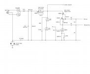
If you need more than 75 mA (power supply shunt regulators), this paralleled version works very well. There is benefit to having the 10M45 on top, as the DN2540 typically has a lower gate voltage for a given current. The more voltage you can provide for the bottom device the better off you are.
I place the 10M45 on the same heatsink, back to back on either side. The drains are at the same potential anyway, so no isolation requirements. I have also moved the zeners to the other side of the gate stopper, contrary to what is shown in the drawing.
I place the 10M45 on the same heatsink, back to back on either side. The drains are at the same potential anyway, so no isolation requirements. I have also moved the zeners to the other side of the gate stopper, contrary to what is shown in the drawing.
Attachments
Thanks Euro21! Do the 10m45s have the same symbols for G, S, and D as a depletion mode mosfet?
When it comes to sand I am a bit new!
The IXYS datasheet calls the terminals G,A,K which correspond to G,D,S i.e. G=Gate
A=Drain
K=Source
The TO-220 pinout is interchangeable with other depletion mode MOSFETs e.g. the Supertex DN2540
Hi and sorry for the revival of an old thread.
I cannot get my cascoded 10M45S to work. The problem is, whatever the resistor value I put (80-300R), the current stays nearly the same (5-6mA). The circuit is used as CCS for a D3A tube and the target is 25-30mA.
Probably I could have screwed something by putting the two packages on the same heat sink without insulation (drain to drain)? When I did so, the current was quite high (50mA) and uncontrollable by the resistor value. Now when I isolated the 10m45s s, the current dropped to 5-6mA and is still uncontrollable by the current value resistor.
I use 1k for grid stoppers.
I have no problem with 10M45S cascodes. I make sure I have lots of headroom, though, on the order of 90-100V.
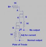
By the way, I'm using the "mu output" of the CCS in my 26 preamp and it sounds excellent, in addition to giving an output impedance of ~1500ohms. I don't hear any degradation versus the plate output - if anything it sounds better. The lower impedance allows me to run the tubes directly into the autoformer volume controls and avoid a separate output transformer. Combined with lossy parafeed the low end extension is -3dB at 4-5Hz.
By the way, I'm using the "mu output" of the CCS in my 26 preamp and it sounds excellent, in addition to giving an output impedance of ~1500ohms. I don't hear any degradation versus the plate output - if anything it sounds better. The lower impedance allows me to run the tubes directly into the autoformer volume controls and avoid a separate output transformer. Combined with lossy parafeed the low end extension is -3dB at 4-5Hz.
Attachments
Datasheet for the Supertex part indicates capacitance drops significantly once you get about 20-25V of headroom. In my uses in about 5 different amps, they run just fine with 20V. I would not suggest running them below 10 if you want decent performance. The lower the capacitance, the higher the output impedance at high frequencies.
- Status
- This old topic is closed. If you want to reopen this topic, contact a moderator using the "Report Post" button.
- Home
- Amplifiers
- Tubes / Valves
- 10m45s cascode diagram?