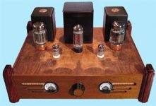
Hello, I am new to discussion forum - building my first amp. I have just completed the enclosure and started wiring the power circuit. The amp I chose to start with is Alex Gendrano's KT88 SE. DIY Single-Ended KT88 / 6L6 / EL34 / 6CA7 Tube Amplifier
I worked through the calculations and have a fairly good understanding of the amp schematic. However, I have one question on the power supply schematic. I have completed the wiring and tested the output voltage. The voltage is from the 5U4-GB is 412VDC. When I connect the filter section the voltage out is 564VDC. Is this correct? The schematic has 400VDC after the circuit. I get the same voltage result if I use the CT of the transformer or as the schematic shows for the 5U4-GB.
I worked through the calculations and have a fairly good understanding of the amp schematic. However, I have one question on the power supply schematic. I have completed the wiring and tested the output voltage. The voltage is from the 5U4-GB is 412VDC. When I connect the filter section the voltage out is 564VDC. Is this correct? The schematic has 400VDC after the circuit. I get the same voltage result if I use the CT of the transformer or as the schematic shows for the 5U4-GB.
I know I've seen very similar little meters on eBay out of Hong Kong.
eBay - New & used electronics, cars, apparel, collectibles, sporting goods & more at low prices
eBay - New & used electronics, cars, apparel, collectibles, sporting goods & more at low prices
eBay - New & used electronics, cars, apparel, collectibles, sporting goods & more at low prices
eBay - New & used electronics, cars, apparel, collectibles, sporting goods & more at low prices
Hello, I am new to discussion forum - building my first amp. I have just completed the enclosure and started wiring the power circuit. The amp I chose to start with is Alex Gendrano's KT88 SE.
I worked through the calculations and have a fairly good understanding of the amp schematic. However, I have one question on the power supply schematic. I have completed the wiring and tested the output voltage. The voltage is from the 5U4-GB is 412VDC. When I connect the filter section the voltage out is 564VDC. Is this correct? The schematic has 400VDC after the circuit. I get the same voltage result if I use the CT of the transformer or as the schematic shows for the 5U4-GB.
Unless you o'scope, you can't trust the voltage reading from the raw output of the FWR, as it's not sinusoidal.
As for the rest, it looks reasonable. Unloaded, you can expect a DC voltage equal to the peak of the AC going in. If you're looking to get 400Vdc under load conditions, then 564Vdc unloaded looks about right. The 5U4GB has a forward voltage of ~100Vdc for an Isurge= 800mA (80% of maximum Isurge per plate).
You probably lose most of the remaining 64Vdc across ripple chokes.
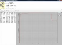
Thank you euro21. I have downloaded the PSU designer but find it a bit confusing to use. Anyway, I have completed the wiring and under load the voltage is at 412. All is working but need to find where the awful hum is coming from.
Did you solve your hum problem? Have you seen this article on grounding?
http://www.geofex.com/article_folders/stargnd/stargnd.htm
Post a few photos of your internal wiring if you are still having problems. This amplifier can be made to be hum free.
Thank you for the link. I did find another artical that helped me locate my ground loop issue, after several hours of hunting. As it turns out, the L and R channel shields were touching and causing a loop. Or, I suppose they were because once seperated the hum went away. There is now only a very slight hum when the pot is at full zero. The hum goes away when slightly above zero, for which it will never be.
This was my first project and am very pleased with the results. I plan on sharing my build in a Gallary post.
This was my first project and am very pleased with the results. I plan on sharing my build in a Gallary post.
- Status
- This old topic is closed. If you want to reopen this topic, contact a moderator using the "Report Post" button.
- Home
- Amplifiers
- Tubes / Valves
- 5U4GB Tube Power Supply Schematic