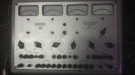
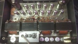
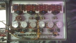
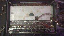
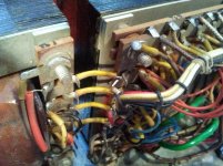
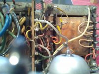
I recently got a Grundig Hartmann&Braun (H&B) 6007 tube regulated PSU. The internals look like they are in fairly decent shape and all tubes seem to be stock (goodies are two EL156 and one EL84, others are PCF80, EF804, 5651). All resistors are 2% MF and range from 1/2W to 1W. The potentiometers on the front feel like they're okay and the switches also seem to work fine. Two of the selenium FW rectifier bridges must have been replaced with Si FW bridges at one point and there are a few wires desoldered from at least two of the transformers. Thus the unit is definitely not in working condition. But at least all fuses are intact...
I'm now trying to decide whether to restore the PSU or to gut it for the parts.
In order to restore it I would at least have to replace all of the selenium rectifier bridges, replace all caps (all of them, period), clean numerous contacts, check all resistors, and figure out what modifications have been done to the wiring, plus maybe get some new tubes. A working HV PSU is likely very handy, but I'm not sure if I would be using it that much.
Gutting it would yield 6 chokes, two EL156 in unknown condition, various other tubes, some decent pots, gorgeous meters and of course some beefy transformers. Maybe a good start for a EL156 SE project, maybe even monoblocks. If the voltage on the transformers goes high enough that is...
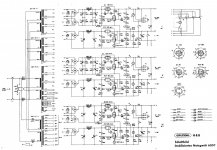
Here's link to the schematic, it's too big to attach: http://www.jogis-roehrenbude.de/Roehren-Geschichtliches/Roehren-Netzteile/H&B-6007.pdf
So what's your opinion, repair it or gut it?
I'm now trying to decide whether to restore the PSU or to gut it for the parts.
In order to restore it I would at least have to replace all of the selenium rectifier bridges, replace all caps (all of them, period), clean numerous contacts, check all resistors, and figure out what modifications have been done to the wiring, plus maybe get some new tubes. A working HV PSU is likely very handy, but I'm not sure if I would be using it that much.
Gutting it would yield 6 chokes, two EL156 in unknown condition, various other tubes, some decent pots, gorgeous meters and of course some beefy transformers. Maybe a good start for a EL156 SE project, maybe even monoblocks. If the voltage on the transformers goes high enough that is...
Here's link to the schematic, it's too big to attach: http://www.jogis-roehrenbude.de/Roehren-Geschichtliches/Roehren-Netzteile/H&B-6007.pdf
So what's your opinion, repair it or gut it?
Attachments
I'll bet you like to save clasic equipment when ever it makes sence, but this might be a time where its best to gut. If you need a high voltage power supply in the future, there are plenty avaiable out there, even ones with filament supply included ect. I noticed the meters right off! Perhaps you could set it aside for a bit and think about specific projects befor you dive into it. This might be a case of how many other projects that you have in the que.
The Grundig 6007 has filament supplies too. It would be a very versatile PSU, but I just don't know how badly it's damaged.
I have a Lambda tube PSU that is good for 300V@400mA that I will restore at some point, and it will be less work since it doesn't even have electrolytic caps to begin with.
I won't find time anytime soon, so there's no pressure. I'm thinking about two monoblocks with some nice CLC power supply and meters for HT and bias current (they are switchable).
Trading sounds interesting too...I'll post some pics of the damages/mods that have been done later.
Here's some additional info: http://radiostollenwerk.de/Images/Netzger%E4t%2060072.pdf
Last edited:
Okay, I'll give this one a try. If I can get it to work it will surely be handy. I examined the circuit and found the following:
Other than that everything looks fine. The resistors should more or less be fine since they're metal film.
The unit contains the following electrolytic caps:
C1 50u 350/385V
C3, C4 50+50u 350/385V
C2 50u 350/385V
C7, C8 50+50u 350/385V
C16, C17 50+50u 350/385V
C23, C24 50+50u 350/385V
C11 50u 350/385V
C13, C12 50+50u 350/385V
C10 50u 350/385V
C20, C19 50+50u 450/550V (!)
C9 100u 12/15V axial
C18 100u 70/80V axial
C23 100u 70/80V axial
And the following non-polar caps (originally paper, all axial):
C5 0.1u 350V
C6 0.1u 500V
C14 0.1u 350V
C15 0.1u 500V
C21 0.1u 350V
C22 0.1u 500V
I'll also have to replace the following rectifier bridges (that's what I'll start with):
B250C125 5 pieces
B250C75 3 pieces
I have one question though: Since the selenium rectifiers drop considerably more voltage than a Si bridge...will this be a mayor problem? What about inrush current? I seem to recall that these Selenium bridges have a somewhat high internal resistance and therefore don't overload the transformer with a high inrush current when initially charging the caps.
Any recommendations?
Tr. 1 has one wire (red) of the third secondary loose.
For some reason someone completely disconnected one primary of Tr. 2
One mains connection going to Tr. 3 was disconnected, thus leaving one primary of Tr. 3 and Tr.1 disconnected.
Two of the Selenium rectifier bridges got replaced with rather small Si rectifier bridges.
Other than that everything looks fine. The resistors should more or less be fine since they're metal film.
The unit contains the following electrolytic caps:
C1 50u 350/385V
C3, C4 50+50u 350/385V
C2 50u 350/385V
C7, C8 50+50u 350/385V
C16, C17 50+50u 350/385V
C23, C24 50+50u 350/385V
C11 50u 350/385V
C13, C12 50+50u 350/385V
C10 50u 350/385V
C20, C19 50+50u 450/550V (!)
C9 100u 12/15V axial
C18 100u 70/80V axial
C23 100u 70/80V axial
And the following non-polar caps (originally paper, all axial):
C5 0.1u 350V
C6 0.1u 500V
C14 0.1u 350V
C15 0.1u 500V
C21 0.1u 350V
C22 0.1u 500V
I'll also have to replace the following rectifier bridges (that's what I'll start with):
B250C125 5 pieces
B250C75 3 pieces
I have one question though: Since the selenium rectifiers drop considerably more voltage than a Si bridge...will this be a mayor problem? What about inrush current? I seem to recall that these Selenium bridges have a somewhat high internal resistance and therefore don't overload the transformer with a high inrush current when initially charging the caps.
Any recommendations?
Attachments
If you haven't found the schematic yet, take a look here:
http://www.jogis-roehrenbude.de/Bastelschule/NGU/Grundig-H&B-6007.gif
You can see, that the Selenium rectifiers are just for the low amp outputs so there should be no problem replacing them with silicon rectifiers, as long as the caps can withstand so higher voltage.
Regards,
Simon
http://www.jogis-roehrenbude.de/Bastelschule/NGU/Grundig-H&B-6007.gif
You can see, that the Selenium rectifiers are just for the low amp outputs so there should be no problem replacing them with silicon rectifiers, as long as the caps can withstand so higher voltage.
Regards,
Simon
I found two of these being sold on ebay recently. One in perfect working condition got almost 400 Eurs, another one in unknown condition got up to 220 Eurs.
I think I could give it a complete overhaul for less than 100 Eurs. I'll first fix the wiring and replace all the rectifiers and see if it turns on, and then decide from there.
I think I could give it a complete overhaul for less than 100 Eurs. I'll first fix the wiring and replace all the rectifiers and see if it turns on, and then decide from there.
Hm, I found that both 600mA fuses on the primary side of the filament supply transformer have failed. Very odd.
I'm still not sure how to address the Selenium bridges' voltage drop. I think they drop somewhere around 20V, the new Si bridges will of course only drop one or two volts. So ideally a dropping resistor would be added after the new Si bridges, but the voltage drop over it would depend on the current being drawn, and that varies of course.
What's the go to approach here? Any experiences?
I have old german tube-radio radio here often playing some music. The original selenium rectifier working just fine.
As long as none of them has failed, I wouldn't change them. Compared to mercury or other heavy metals, selenium is harmless. As long as you don't crush them and inhale the dust.
I have been working with equipment which has selenium rectifiers in them since I was 16. The same with asbestos (transformer heat cover). As long is you don't disassemble these things, everything is fine.
When you want to change them so bad, you should at least keep them as spares for vintage tube gear. But as I said, when you see selenium as a problem, then you should be scared to death by mercury vapor rectifiers")
There is no problem with resistors. Selenium doesn't have a higher threshold only a higher differential inner resistance.
And since this PSU is regulated, every drop before the regulation shouldn't matter.
As long as none of them has failed, I wouldn't change them. Compared to mercury or other heavy metals, selenium is harmless. As long as you don't crush them and inhale the dust.
I have been working with equipment which has selenium rectifiers in them since I was 16. The same with asbestos (transformer heat cover). As long is you don't disassemble these things, everything is fine.
When you want to change them so bad, you should at least keep them as spares for vintage tube gear. But as I said, when you see selenium as a problem, then you should be scared to death by mercury vapor rectifiers
There is no problem with resistors. Selenium doesn't have a higher threshold only a higher differential inner resistance.
And since this PSU is regulated, every drop before the regulation shouldn't matter.
Do you have anything comparable (my friends father has two tube testers, a stack of volt meters for tube amp building, and volumes of printed material), in that you will not be missing such a fine piece of equipment? If you don't want it, then sell it or take it apart for parts. If however, you like the unique look and history of it, then keep it. This definitely is something you don't find often.
I'd keep it and fix it. If not using, fix it still, and then sell.
I'd keep it and fix it. If not using, fix it still, and then sell.
You're right, overtheairbroadcast. I have looked into some projects that could be realized with this PSU and if I can get it to run it will become very handy.
I very much distrust selenium rectifiers, thus they will all be replaced with a 1000V (V_RRM) 8A (I_F) rectifier bridge (GBU8M from General Semiconductor). Maybe I'll ad dropping resistors after the rectifier bridges. I think they should be on the order of 100R and rated 3W (Vishay Phoenix PR03).
I will also replace the bleeder resistors of the EL156 circuit with 220k 3W Vishay PR03 resistors, the old ones are bent and possibly damaged. I will see how the caps perform when slowly firing up the PSU with a variac, maybe they can be reformed to a certain extent.
I have two questions:
Can I safely increase the capacitors at the regulators' outputs (C5, C14, C21; originally 0.1uF 350V) to 1.5uF? I have several Arcotronics MKP C.4G 1.5uF 850V capacitors and would like to use them. Do I risk damage or instability by adding so much capacitance?
Is it possible to wire the two EL156 circuits in series to create a +/- 150V bipolar HV supply? It looks like the circuits themselves are not referenced to ground, so it should be possible...
http://www.jogis-roehrenbude.de/Bastelschule/NGU/Grundig-H&B-6007.gif (Thanks again for the link, Simon!)
Attachments
You're right, overtheairbroadcast. I have looked into some projects that could be realized with this PSU and if I can get it to run it will become very handy.
Glad I could be of some assistance, hope it turns out well for you and that you have fun doing it!
And don't forget to post pictures along the way.
- Status
- This old topic is closed. If you want to reopen this topic, contact a moderator using the "Report Post" button.
- Home
- Amplifiers
- Tubes / Valves
- Grundig H&B 6007 tube power supply - Repair or gut for parts?