Hello,
I have a a pair of Wright Audio Mono 25 amps that both have a significant hum. The Wright Audio Mono 25 uses a Williamson based circuit. The hum has become more bothersome as I moved to more efficient speakers (Fostex fe168 Sigma in a BIB).
There is only a mild hum when the preamp is not connected, but increases when the rca is inserted. The hum reduces as the input pot is attenuated. Because of this, I suspect a ground loop, and am considering changing the ground to a star grounding.
Here is a overall picture of the amp:
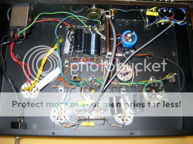
Here is a close up of the power supply:
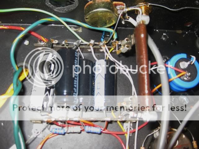
Note that the current ground is not based on the ground of the first PS cap. I believe the red/yellow is the center tap of the High voltage output from the power xfmr. The white wires are for the ground. The rca is grounded to the chassis.
From what I understand of star grounding, I have the following plan:
1. Cut ground wire from cap bank to potentiometer
2. Cut ground wire from RCA to Output XFMR
3. Cut the two white ground wires from the cap bank that go to the input and phase splitter stages, respectively.
4. Isolate RCA from the Chassis
5. Drill hole in chassis near incoming AC to create chassis connection
6. Run ground wires from new chassis connection to cap bank, output xfmr, rca, input stage and phase splitter stage.
Does this seem like a good plan? Is star grounding likely to reduce my hum problem?
Should I add the ground of the first cap to the star ground as the first connection, and have the other bank added as a local node (run a wire from the star ground to the ground wire on the cap bank)? I am confused because the choke does have some resistance, so I'm not sure what the result would be, but the keen webpage on star grounding is clear that the power xfmr center tap and ground of first power supply capacitor should be the first .
One last question... I am using a 300K ohm resistor to drain the caps, but some residual voltage remains, about 30 mV. Is this a problem, or can I safely work on the caps with that small voltage present?
Thanks in advance.
Mark
I have a a pair of Wright Audio Mono 25 amps that both have a significant hum. The Wright Audio Mono 25 uses a Williamson based circuit. The hum has become more bothersome as I moved to more efficient speakers (Fostex fe168 Sigma in a BIB).
There is only a mild hum when the preamp is not connected, but increases when the rca is inserted. The hum reduces as the input pot is attenuated. Because of this, I suspect a ground loop, and am considering changing the ground to a star grounding.
Here is a overall picture of the amp:
Here is a close up of the power supply:
Note that the current ground is not based on the ground of the first PS cap. I believe the red/yellow is the center tap of the High voltage output from the power xfmr. The white wires are for the ground. The rca is grounded to the chassis.
From what I understand of star grounding, I have the following plan:
1. Cut ground wire from cap bank to potentiometer
2. Cut ground wire from RCA to Output XFMR
3. Cut the two white ground wires from the cap bank that go to the input and phase splitter stages, respectively.
4. Isolate RCA from the Chassis
5. Drill hole in chassis near incoming AC to create chassis connection
6. Run ground wires from new chassis connection to cap bank, output xfmr, rca, input stage and phase splitter stage.
Does this seem like a good plan? Is star grounding likely to reduce my hum problem?
Should I add the ground of the first cap to the star ground as the first connection, and have the other bank added as a local node (run a wire from the star ground to the ground wire on the cap bank)? I am confused because the choke does have some resistance, so I'm not sure what the result would be, but the keen webpage on star grounding is clear that the power xfmr center tap and ground of first power supply capacitor should be the first .
One last question... I am using a 300K ohm resistor to drain the caps, but some residual voltage remains, about 30 mV. Is this a problem, or can I safely work on the caps with that small voltage present?
Thanks in advance.
Mark
You can work on the caps with 30mv present. I f it still bothers you, clip it to ground, just don't forget the wire in there when your done.
I just solved a hum problem with an amp on breadboard.
At the the end of the day the problem went away when I Plugged the amp into another outlet. None of the other fixes would touch it. It did not hum in that outlet until I went to a higher voltage transformer. None of the "RFI" fixes were doing it for me, changing my ground scheme did not fix it.
So just try that first for the heck of it, then hack the amp if it does not work.
Have fun.
Thanks for the reply globug.
I've tried cheater plugs without success, and also tried the amps in the two other outlets in the listening room. I could try them in the basement with the 20 amp circuit without anything else on it and see what happens.
I'm still wondering about grounding at the first capacitor.
I've tried cheater plugs without success, and also tried the amps in the two other outlets in the listening room. I could try them in the basement with the 20 amp circuit without anything else on it and see what happens.
I'm still wondering about grounding at the first capacitor.
The connection between the first cap and the transformer CT should not go to the star point. Instead, a connection to the star point should be tee'd off this. This keeps charging pulses well away from the star point. Personally, I would not make the star point a chassis connection as this can mix up the safety and signal grounds. The star point is a signal ground. It needs to be connected to the safety ground by some means, but the star point should not be the safety ground. Grounding gets more complicated with dual mono amps, as it is hard to avoid introducing ground loops when you connect the two stereo channels together.
If the hum changes with the pot position, then is incoming from the previus stage via signal wires. You don't have any coaxial wires in there (except the one from pot to first tube), or at least twisted pairs, tubes are working with high impedances (what's the input pot value, 100K?) no wonder you pic-up hum.
Try to arrange the ground differently - the input pot ground should be connected to the input stage one with thiker wires. Output stage ground should go straight to the power supply via a separate wire - right now looks like if flows thru that thin bare wire that is the input ground too?
Try to arrange the ground differently - the input pot ground should be connected to the input stage one with thiker wires. Output stage ground should go straight to the power supply via a separate wire - right now looks like if flows thru that thin bare wire that is the input ground too?
Last edited:
DF96 and sonic_real_one, thanks for your replies.
DF96, I will remove the ac ground wire from the capacitor bank, and attach it to the chassis on its own.I'm not sure what you mean by "Tee it off". It occurs to me however that I can't ground the first capacitor with the ones after the choke, because that would effectively bypass the choke. Probably I should leave the first cap alone.
Sonic_real_one, are you saying the hum is not coming from the amp? I suppose I could try hooking up a cd payer directly. Hum, although present is at least tolerable on my 2A3 and my solid state amps.
Yes the input pot is 100K and yes that thin bare wire is the ground for the input, phase splitter, power supply and output xfmr. I'm not sure where the ground for the output stage is.
By 'tee' I mean put a wire from transformer CT to reservoir cap -ve terminal. Then somewhere along this wire attach another wire which goes to the star point. Other caps can go to the star point. Keep charging pulses well away from the chassis. The chassis is safety ground, not signal ground. I suspect you need to do some more reading about audio grounds, both within and between equipment.
Sometimes external ground loops develop from currents circulating between the incoming ground of a cable tv connection and the ground with your AC power connection. I once built someone a shielded box with a small ferrite r.f. transformer (like a 300 ohm to 75 ohm matching transformer, but wound 1 to 1 ratio) for isolation. Some cable company equipment may expect a DC connection for other reasons though. Some other equipment, in attempts to filter noise, may have capacitors from both sides of the power line to ground causing some current flow. Keeping that power cord ground connected to the filter, but floating it from the rest of the units grounds with a 10 to 100 Ohm resistor bypassed with a small, say .001 uF capacitor in between AC ground and circuit ground cures that. When possible, plug everything involved with your system into the same power strip. It degrades low-end response, but if equipment that you can't float or modify is giving trouble, a last resort is to couple the audio through transformers. That works okay with most consumer gear, but few transformers are high enough impedance to work well with a tube preamp that has a very high output impedance (no cathode follower buffer).
Check what hum level you get when you ground the input valve from grid to 0V at the cathode bias connection point. If that achieves negligible hum level then focus on the input cabling/connection. If that hum level is not negligible, then focus is more on the ways that hum can inject to the first stage (there are a few ways). It appears to be all about the first stage!
The heater wiring is not good either. Get the book Building Valve Amplifiers by Morgan Jones and rebuild the amp. The problem is the heater wiring is done right below the components for the driver stage. Very bad practice! Heater wiring should be placed against the edge of the chassis. So when rebuild the amp turn the tube sockets so the filament terminals points against the edge. Use as thick wire as possible and twist it tight.
The wire from the transformer should go to the output tube(s) first and then to the driver tubes. Wire the driver tube with most gain as the last tube in the chain. Get the book...
As the hum increase when your preamp is plugged in can be a ground loop or the preamp is not hum free. Try another preamp or power amp to figure out which of your amps causes most hum problems.
Try this:
deattach the interconnect cable between the preamp and poweramp.
Short the input of power amp.
Turn both amps on.
Now measure the ac voltage difference between RCA ground on the two amps.
Now unplug one of the amps and reverse the wall plug.
Turn on and measure again.
You want the lowest ac voltage between your equipment as this adds hum to the signal. This kind of problem is avoided using balanced equipment and cables.
DF96, thanks for the clarification. OK, single chassis ground to which the safety ground is directly attached, and which also has a connection to the star ground.
Riccoryder, I don't have cable attached to my stereo system, but I will try a more systematic approach to relationship of connections to resultant hum.
Trobbins, are saying to measure the hum at pin 6 when pin 4 is shorted to ground?
Nelson, thanks for the advice. I will look for the book you recommended, as I have seen references to it while lurking here. I think I will at least try to tighten up the twist of the smaller wires. Would it be worthwhile to re-route the heater wiring away from the input at the expense of longer wiring?
I did notice that the shielded wire from the input section to the output transformer has the shield connected at the input section. I believe this is the global feedback loop. So, what I know about shielding suggests that the shield should be connected at the signal source, which is the output transformer. Is it advisable to change the shielding so that is connected on the OPT side?
I do want to mention that these amps were prototypes built by George Wright, and probably not representative of his commercial product. (Note to self: do not buy another prototype). I have used it in the past with two other preamps with the same amount of hum.
The feedback wire does not really need to be shielded, but if done properly it need not do any harm. Ensure that the feedback resistor is at the input end of the feedback wire, and keep the wire clear of power wiring. However, it is important that the ground reference for the feedback is the same as the ground reference for the input signal. I achieved this by using the ground wire for the feedback as the only grounding for the OPT secondary.
Testing assumptions
I tried some different combinations of source components directly into the amp. I have a Bottlehead Seduction phono, Satellite radio and cd. I used the amp input pot to control sound.
There was a good deal of tube rush with the phono, but no hum or buzz with any of these.
I hooked the preamp back in, and tried each source component alone, and even with no source. As long as the preamp output is connected to the Wright Mono 25, there is hum, affected by the input pot of the amp. The hum is present even with the preamp powered off and unplugged.
I'm not sure what this means since I had the same issue with a previous preamp. Should I be looking at improving the preamp?
The hum occurs regardless of the source connection to the preamp. The hum occurs if and only if the preamp output is connected to the amps. Surprising to me was that the hum occurred even if the preamp was turned off.
I'm going to check the bottlehead forum for foreplay hum issues. An initial search shows lots of problems, with different fixes.
Thanks to all who have replied so far, it is greatly appreciated. I feel some progress has been made to figuring out the cause of the hum, if not the solution.
I'm going to check the bottlehead forum for foreplay hum issues. An initial search shows lots of problems, with different fixes.
Thanks to all who have replied so far, it is greatly appreciated. I feel some progress has been made to figuring out the cause of the hum, if not the solution.
- Status
- This old topic is closed. If you want to reopen this topic, contact a moderator using the "Report Post" button.
- Home
- Amplifiers
- Tubes / Valves
- Advice needed for hum reduction