Success: Help with Preamp/Amp hum
I haven't posted much lately as I'm been busy with other things, but I recently rebuilt my phono/pre in a new shielded chassis and have created a problem with hum. Any help would be very much appreciated.
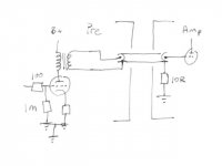
The phono and pre are scratch builds around ECC83/phono and 12B4/pre. The phonostage has no noticeable hum. The pre does. The pre is transformer out with a Sowter 9705s 4:1 40H 30mA.
The amp is a WAD6550.
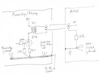
I've attached a simple drawing of the grounding. You can see I have no network at the transformer out. It goes directly to the RCA and the ground is earthed via a 10R signal lift in the amplifier chassis (in accordance with WAD instructions).
Out of the speakers, I'm getting about +25db's around 100-120Hz. I can measure 21 and 29mV AC at the amp speaker posts. (No noticeable difference if it is CD or Phono selected.)
Trying to track the hum down, I've found the following:
1. Shorting the interconnect neg at the preamp to ground causes even more hum. (Causes an earth loop?)
2. Amp with the inputs shorted to ground gives no hum (the amp is really quiet).
3. Measuring AC at the end of the disconnected interconnect (amp side) with the preamp on, I get almost nothing, 0.3mV.
4. Measuring AC at B+ prior to the pre output transformer is 0.2mV.
5. Shorting the grid on the 12B4 pre made no change in hum.
The phono/pre power supply is in a separate chassis with all grounding from the phono/pre chassis back to that.
I used a bus bar (heavy copper wire) in the pre with all the small signals at one end starting with the phonostage, then pre and then filtering (some final stages in the pre chassis) and chassis earth at the other end returning to the umbilical to the PS chassis.
Any ideas?
Thanks,
Dan
I haven't posted much lately as I'm been busy with other things, but I recently rebuilt my phono/pre in a new shielded chassis and have created a problem with hum. Any help would be very much appreciated.
The phono and pre are scratch builds around ECC83/phono and 12B4/pre. The phonostage has no noticeable hum. The pre does. The pre is transformer out with a Sowter 9705s 4:1 40H 30mA.
The amp is a WAD6550.
I've attached a simple drawing of the grounding. You can see I have no network at the transformer out. It goes directly to the RCA and the ground is earthed via a 10R signal lift in the amplifier chassis (in accordance with WAD instructions).
Out of the speakers, I'm getting about +25db's around 100-120Hz. I can measure 21 and 29mV AC at the amp speaker posts. (No noticeable difference if it is CD or Phono selected.)
Trying to track the hum down, I've found the following:
1. Shorting the interconnect neg at the preamp to ground causes even more hum. (Causes an earth loop?)
2. Amp with the inputs shorted to ground gives no hum (the amp is really quiet).
3. Measuring AC at the end of the disconnected interconnect (amp side) with the preamp on, I get almost nothing, 0.3mV.
4. Measuring AC at B+ prior to the pre output transformer is 0.2mV.
5. Shorting the grid on the 12B4 pre made no change in hum.
The phono/pre power supply is in a separate chassis with all grounding from the phono/pre chassis back to that.
I used a bus bar (heavy copper wire) in the pre with all the small signals at one end starting with the phonostage, then pre and then filtering (some final stages in the pre chassis) and chassis earth at the other end returning to the umbilical to the PS chassis.
Any ideas?
Thanks,
Dan
Attachments
Last edited:
Have you tried separating the small signal grounds and taking them back to the power supply ground with their own separate conductor?
AC and other time-varying ground-return currents induce voltages across the ground-return conductor's inductance and resistance. Those voltages appear back at the non-PSU-ground end of the ground-return conductor. Since that includes the ground reference point for your grid input resistor, those voltages will be arithmetically summed with your input signal!
That is why star grounding concepts should be used.
Last edited:
Have you tried separating the small signal grounds and taking them back to the power supply ground with their own separate conductor?
AC and other time-varying ground-return currents induce voltages across the ground-return conductor's inductance and resistance. Those voltages appear back at the non-PSU-ground end of the ground-return conductor. Since that includes the ground reference point for your grid input resistor, those voltages will be arithmetically summed with your input signal!
That is why star grounding concepts should be used.
I've always had good luck with using a bussbar approach (read in MJ 2nd edition, I think, don't see it in my 3rd ed) where you start at one end with the low current signals (grid leak) and work your way over to the powersupply filter caps and chassis ground.
Last edited:
I've always had good luck with using a bussbar approach (read in MJ 2nd edition, I think, don't see it in my 3rd ed) where you start at one end with the low current signals (grid leak) and work your way over to the powersupply filter caps and chassis ground.
That would minimize the problem with the shared conductor length. But was that ever with a much longer shared ground-return conductor going back to an external PSU?
Anyway, why degrade performance when it's avoidable? Sometimes it might not be noticeable but it will always be creating a problem to some extent.
Last edited:
That would minimize the problem with the shared conductor length. But was that ever with a much longer shared ground-return conductor going back to an external PSU?
great point!!!!!
Well changed the grounds around separating the later stage filter caps from the signal grounds in the preamp chassis. No joy.
When I wave the preamp chassis around the power supply chassis, I get lots of nice hum. Especially when the pre output transformers are close to the power transformers.
I get a nice reduction of hum by putting 100R across the output transformer out terminals.
Back to the drawing board.
When I wave the preamp chassis around the power supply chassis, I get lots of nice hum. Especially when the pre output transformers are close to the power transformers.
I get a nice reduction of hum by putting 100R across the output transformer out terminals.
Back to the drawing board.
Last edited:
Got it.
The Q on my preamp power supply was all messed up.
The first stage filter is choke input and a cap. 20H and 100uF. The internal resistance of the choke is 182R. That all calculated out to Q=2.5
I saw on older notes I had 500R additional resistance in the snubber circuit that wasn't there now.
So I put in a 500R resistor before the choke and after the 220nF cap. After the choke, have another 220nF cap.
I also increased the capacitance to 200uF for good measure.
This brought Q down to 0.46, under the 0.5 limit that I understand.
No more hum!
Always something other than you think.
Thanks!
@it_texan
Please, can you explain me a bit more about Q and calculation. I don't know much about all of this, made some preamp and amp, and have a bit of hum in both. Preamp is basicly worst as it have hum per one channel while volume is zero and starting to rise on other channel when I rising up volume.
Thanks!
I highly recommend Morgan Jones' book "Valve Amplifiers."
That's where I've gotten most of my understanding of power supplies and circuits for valve amps. (I can now understand half the stuff written here!)
In Morgan's third edition, page 322 he writes about Q as a measurement of of a low freq peak in a choke input power supply filter.
In order to critically damp the resonance, Q should be measured at or below 0.5.
Formula is:
Q = (1/Rdc) x (sq rt of L/C)
where Rdc is the internal dc resistance of the choke.
L in henries, and
C in farads
He recommends to lower Q by adding series resistance before the choke and putting snubber caps of 220nF before the extra resistance and after the choke.
Hope that helps.
Oh and if it's not on both channels, maybe not the power supply?
Well, back to my "problem."
My above fix did improve things dramatically. But I can still hear noticeable hum!!!
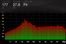
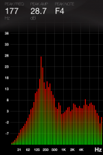
I'm getting a peak hum at 177Hz at +27dB
I've got the Octave app on my iphone which I've been using to try to measure improvements as I try new things. (Pictures!!!!)
I do guess work with no real tools to measure what is going on.
I put in a second filter in-between the original 1st and second stages.
Now I have:
190-0-190 VAC into a EZ81
1st stage
500R + 20L (internal 182R) with a .47uF before and a .22uF after
then 2x100uF with 2x1uF and .022uF bypass caps
100k bleeder resistor
2nd stage
1.5L (internal 51R) then 3x100uF with 3x1uF bypass caps
and last stage
5L (internal 238R) then 100uF and 24uF and 1uF bypass cap.
This mess is B+ into Hammond preamp output transformers (rated at 30mA each)
I've got 108V at the 12B4A anodes with 11-12V at the cathode and 510R there. So about 23-24mA per valve.
Can I be inducing hum into the OPT????
I'm truly at a loss. I'm I going to have to look at the grounding? Please no!
My above fix did improve things dramatically. But I can still hear noticeable hum!!!
I'm getting a peak hum at 177Hz at +27dB
I've got the Octave app on my iphone which I've been using to try to measure improvements as I try new things. (Pictures!!!!)
I do guess work with no real tools to measure what is going on.
I put in a second filter in-between the original 1st and second stages.
Now I have:
190-0-190 VAC into a EZ81
1st stage
500R + 20L (internal 182R) with a .47uF before and a .22uF after
then 2x100uF with 2x1uF and .022uF bypass caps
100k bleeder resistor
2nd stage
1.5L (internal 51R) then 3x100uF with 3x1uF bypass caps
and last stage
5L (internal 238R) then 100uF and 24uF and 1uF bypass cap.
This mess is B+ into Hammond preamp output transformers (rated at 30mA each)
I've got 108V at the 12B4A anodes with 11-12V at the cathode and 510R there. So about 23-24mA per valve.
Can I be inducing hum into the OPT????
I'm truly at a loss. I'm I going to have to look at the grounding? Please no!
Attachments
This mess is B+ into Hammond preamp output transformers (rated at 30mA each)
no! Sowter.
I had one side of the bussbar in the power supply anchored to a transformer.
Got rid of that and a bit better.
So I think a rethink of my grounding in the power supply is in order. (I never listen gootee!)
But a bit better now.
Got rid of that and a bit better.
So I think a rethink of my grounding in the power supply is in order. (I never listen gootee!)
But a bit better now.
Attachments
Last edited:
Yeah, now I'm guessing it's "enclosed loop area(s)".
Any time-varying EM or M field in the air will induce a corresponding current in any conductive loop. And, conversely, any time-varying current in a conductive loop will induce a corresponding time-varying EM or M field in the air. (See Faraday's Law, or Maxwell's Equations, if interested.)
Any impedance in the loop would then have a voltage induced across it (even the distributed impedance of just the conductors). It wouldn't take much current through that 1M input resistor to have a significant-enough voltage applied to the grid by the unwanted induced current. An unwanted corresponding voltage could also be induced across the source impedance.
Think of everything in terms of pairs of conductors, e.g. input signal and its ground, DC or AC power to heaters and their return, AC mains pair, Rectifier output and its ground, DC power and ground/return, outputs and their ground/return.
The conductors for each pair must (ideally, at least) never physically separate from each other. Each pair should be tightly twisted together, if possible, for as long as possible. (Alternatively, you could use shielded twisted pair. But remember that the shield is NOT for the ground conductor of the pair, and the shield should be connected to chassis at one end only and to nothing on the other end.)
Any pair that has any enclosed loop area (i.e. the conductors are physically separated, at some point) WILL both receive and transmit (but typically only one of those modes will be a potential problem, for each pair).
Also, keep all small-signal and sensitive pairs far away from any high-current or highly-dynamic current pairs (and devices). If they must approach each other, they should be perpendicular.
You might now have to go to greater lengths, since you like the bussbar approach. I hope I'm wrong.
Signal input and signal input ground, for example (which should use isolated jacks and should not be connected to the chassis, or anything else, yet), should be tightly twisted (or twisted and shielded), ALL the way to the 100R resistor. For overkill, I would then wrap the signal input ground conductor around the 100R and the 1M and their leads, all the way to where it connects at the base of the 1M. (And ideally that ground should return to the PSU "star ground point" ALONE, i.e. not sharing any length of conductor with any other ground return. The star ground point will probably be at the end of a very short stub off of the filter caps' ground, somewhere after the first cap.)
Are your heater supply wires physically separated from their ground return wires? (Better if not separated at all.)
Are the wires from the AC transformer to the rectifier twisted together? (Good if so.)
Are the wires from the rectifier to the filtering twisted together? (Good if so.)
Are the DC and ground kept as close to each other as possible, as they wend their way through the filtering sections after rectification? (Good if so.)
DC supply pair, after the filtering?
Outputs pairs?
Any other pairs?
In the case of PCB traces, ideally the two conductors of each pair would be right over each other, on opposite sides of the PCB, if two-sided, or running parallel with minimal spacing between them, if one-sided. (Obviously, using multilayer PCBs with power and ground planes could make life much easier. But I'm assuming we don't have that option.)
Anyway, you probably get the idea. Look for the obvious ones first and correct one pair at a time and test to see if there was any effect.
By the way, you can probably tell if the input signal/gnd pair is causing part of the problem by testing with the inputs open and then with them shorted (or with a source connected). If the problem is worse with the source than when open (loop closed, sort of), try a short instead of the source. If still worse than when open, it's likely they are acting as an antenna, i.e. have enclosed loop area that needs to be eliminated, per the above.
Last edited:
gootee, time to retire for the night. just read your post. tomorrow....
I'll leave you with this.
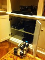
1st picture of the preamp power supply pulled away as far as I can.
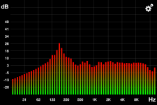
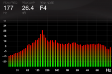
2nd picture of the effect of 180Hz dB's - much lower
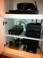
3rd picture of the preamp power supply back in the cabinet
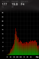
4th picture of the effect on 177Hz dB's - much higher.
I'll leave you with this.
1st picture of the preamp power supply pulled away as far as I can.
2nd picture of the effect of 180Hz dB's - much lower
3rd picture of the preamp power supply back in the cabinet
4th picture of the effect on 177Hz dB's - much higher.
Attachments
- Status
- This old topic is closed. If you want to reopen this topic, contact a moderator using the "Report Post" button.
- Home
- Amplifiers
- Tubes / Valves
- Help with Preamp/Amp hum