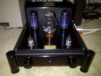
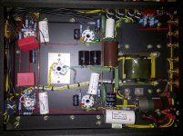
I recently purchased a Meixing MC34-A07 single ended EL34 integrated amp from China. It looked like a good modification platform, i don't have facilities to do a nice chasis, so pre-built was a good idea for me. The price was right (US$579 delivered) and the build quality is very nice. Note: The MC34-A07 is no longer in production but there are still some new ones out there. The site i bought mine from said they had 19 left.
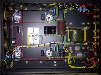
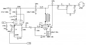
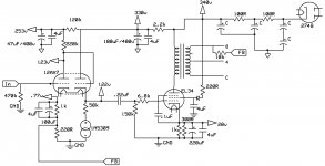
I let it burn in for a while until it seemed to settle out. Then i dug in and traced it out. The schematic is not exact (e.g. there are some things going on in the FB circuit that i didn't trace out, and the 274B symbol is wrong). The circuit is a pretty conventional 12AX7 1/2 voltage amp, 1/2 cathode follower, feeding an EL34 triode strapped. PS is 274B rectified with a 3 stage RC filter (4 if you include the extra isolation for the 12AX7). Global feedback is from the secondary of the OPT to the cathode of the 12AX7 voltage amp. The EL34 suppressor grid is tied directly to +V (instead of the plate), and the screen grid is tied directly to ground instead of the cathode : both seem "unusual" to me.
I have to say that stock it sounds pretty nice. Nice timber, decent detail, very listenable. But what can i say? I like to play") I'm posting here because i'd love to have input from the gurus as i go through this adventure. My only test equipment is DVM, an old Tektronics 100Mhz scope, and a signal generator function in my Squeezebox.
I'm posting here because i'd love to have input from the gurus as i go through this adventure. My only test equipment is DVM, an old Tektronics 100Mhz scope, and a signal generator function in my Squeezebox.
My setup includes Hornshoppe speakers (with bass "augmenter"). Source is a modified Squeezebox Duet (). Maybe one day i will resurrect my old turntable and build a phono stage...
With my setup, this amp has gain to burn. So i decide to start by simply lifting a leg of the cathode resistor bypass caps on both the voltage amp and output stage. Gain loss was minimal, but it took on a much leaner bass presentation. I based this 1st mod on the assumption that the main purpose of the bypass caps is to boost gain at the sacrifice of some cap induced DA distortion. Maybe it is interacting with the feeback circuit?
My mod plans so far include:
Comments?
I let it burn in for a while until it seemed to settle out. Then i dug in and traced it out. The schematic is not exact (e.g. there are some things going on in the FB circuit that i didn't trace out, and the 274B symbol is wrong). The circuit is a pretty conventional 12AX7 1/2 voltage amp, 1/2 cathode follower, feeding an EL34 triode strapped. PS is 274B rectified with a 3 stage RC filter (4 if you include the extra isolation for the 12AX7). Global feedback is from the secondary of the OPT to the cathode of the 12AX7 voltage amp. The EL34 suppressor grid is tied directly to +V (instead of the plate), and the screen grid is tied directly to ground instead of the cathode : both seem "unusual" to me.
I have to say that stock it sounds pretty nice. Nice timber, decent detail, very listenable. But what can i say? I like to play
I'm posting here because i'd love to have input from the gurus as i go through this adventure. My only test equipment is DVM, an old Tektronics 100Mhz scope, and a signal generator function in my Squeezebox.My setup includes Hornshoppe speakers (with bass "augmenter"). Source is a modified Squeezebox Duet (). Maybe one day i will resurrect my old turntable and build a phono stage...
With my setup, this amp has gain to burn. So i decide to start by simply lifting a leg of the cathode resistor bypass caps on both the voltage amp and output stage. Gain loss was minimal, but it took on a much leaner bass presentation. I based this 1st mod on the assumption that the main purpose of the bypass caps is to boost gain at the sacrifice of some cap induced DA distortion. Maybe it is interacting with the feeback circuit?
My mod plans so far include:
- Shorting out the volume control. I'm always amazed at how much is lost thru a mechanical pot.
- Diode screen grid mod (http://oestex.com/tubes/oes.html).
- Hazen suppressor grid mod (http://www.decware.com/newsite/paper146.html).
- CCS or LED in the voltage amp cathode leg.
- Trying an SRPP circuit in the voltage amp. Maybe start with using the 12AX7, or a mosfet in the upper section, then if
the filament xfmr can handle it, try using a 6N1P in place of the 12AX7...
Comments?
Attachments
Last edited:
Report after an evening of listening to the amp with all the cathode bypass caps removed. Bass and lower mid is noticeably leaner. But upper end is also nicely clearer. I did a little reading on this mod, it appears that part of what i am hearing IS due to the interaction with the FB network. Removing the bypass cap from the input voltage amp stage also reduces the gain of the feedback injection point.
Ok, it was interesting.
Ok, it was interesting.
DA doesn't cause distortion; it is a linear mechanism.
Your description of EL34 grids does not tally with the circuit. You said it was 'triode strapped' then described a peculiar (non-triode) grid arrangement. The circuit shows a slightly-modified pentode connection. So which is it?
Your description of EL34 grids does not tally with the circuit. You said it was 'triode strapped' then described a peculiar (non-triode) grid arrangement. The circuit shows a slightly-modified pentode connection. So which is it?
Yep you're right, my description is wrong. Not triode strapped. What the schematic shows is correct in this case.
And on the effect of removing the cathode bypass caps: seems it also raises the output impedance and reduces damping factor of the output stage. I'll probably put the electrolytic caps back in the circuit and maybe try bypassing them with polyprop's...
And on the effect of removing the cathode bypass caps: seems it also raises the output impedance and reduces damping factor of the output stage. I'll probably put the electrolytic caps back in the circuit and maybe try bypassing them with polyprop's...
Last edited:
Yes, you have a pentode output stage. It will have high output impedance, although reduced by the NFB. Removing the cathode bypassing will increase it still further.
The voltages around the first stage don't look quite right. Are you sure it has a 1M anode resistor? That would put the current rather low, so the valve would be near cutoff and probably distort quite badly. NFB would help clean it up.
My gut feeling is that whoever 'designed' this amplifier needs to do a bit more reading of both textbooks and data sheets.
All the cathode bypass caps have been restored. Ran it that way for several hours and to my ear is a much more balanced voicing (wish i had a way of running freq response charts to see exactly what it was doing.)
Next i installed polypropylene bypass caps on all electrolytic power supply filter caps and the electrolytic cathode bypass caps. That had the expected result of opening up the sound stage presentation and improving clarity. Much more detail and less grunge.
But there is SO much unnecessary gain. Any suggestions on trading gain for linearity (without more feedback)?
Also, having the EL34's screen grid tied to B+ worries me. It's not supposed to exceed the anode voltage, otherwise it will draw current. Is that just bad design or am i missing something?
Last edited:
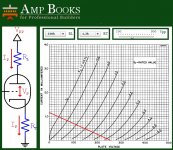
You could increase gain and linearity by adjusting the 12AX7 anode circuit. It needs a bit higher anode voltage, to get it away from the grid current region. Also a higher anode load would reduce distortion at little. Try changing the 220k supply resistor to 100k. Then the 150k anode resistors to 220k or 270k. The cathode follower cathide resistor may need to be increase a bit - say 120k.
Alternatively use the same circuit but with a different lower gain valve and, probably, lower resistor values.
Alternatively use the same circuit but with a different lower gain valve and, probably, lower resistor values.
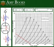
Here's my results so far after playing with various mods. I took DF96's advises on improving the 12ax7's operating points, and included the operating point chart for before/after using Amp Books for Professional Builders calculator.
DF can you comment on those? Is this the result you were expecting?
This seemed to present a more relaxed sound. But i think there was too much being lost in the cathode follower to really be able to discern all that this change did.
I had experience from many years ago with 12ax7 cathode followers. In a word (or two): they suck! But a friend recommended i try putting a CCS in the cathode leg. It truly makes an astonishing difference. It's as if someone pulled a very thick blanket out from in front of the speakers. I kind of wish i had done this mod first, it would have made it easier to hear differences with the rest of the mods i tried (including the EL34 screen and suppressor grid mods.)
What i learned from this is that the 2nd stage (cathode follower) is the weakest link in this amp. And i doubt that it is really needed, or "would be needed" if an input tube with a little higher current capability was used. So...
Future
Maybe an SRPP or Mu follower for the input stage? I've seen a few circuits both here and on other sites using a 12ax7, but since i really don't need so much gain here, i'm thinking a better tube is in order here. Any suggestions?
Attachments
- Status
- This old topic is closed. If you want to reopen this topic, contact a moderator using the "Report Post" button.
- Home
- Amplifiers
- Tubes / Valves
- Starting a Meixing MC34-A07 modification project