Greetings,
I am building a tube preamp and it would be nice to roll in the baffle step compensation into the preamp circuit.
I have a 12AU7A on the preamp front end. I only need one half of the triode for each channel and I thought it would be good to employ that second triode, but I am unsure about the topology and circuit values.
My baffle is 2' wide, so my BSC F3 should be 190 Hz (380/2 feet = 190 Hz).
The OUT goes to the next stage in the preamp circuit.
I need to know:
1. Is the circuit topology valid?
2. What or better yet, how do I calculate the values for R6, R7, and C3?
Any other thoughts?
Thanks in advance!
I am building a tube preamp and it would be nice to roll in the baffle step compensation into the preamp circuit.
I have a 12AU7A on the preamp front end. I only need one half of the triode for each channel and I thought it would be good to employ that second triode, but I am unsure about the topology and circuit values.
My baffle is 2' wide, so my BSC F3 should be 190 Hz (380/2 feet = 190 Hz).
An externally hosted image should be here but it was not working when we last tested it.
The OUT goes to the next stage in the preamp circuit.
I need to know:
1. Is the circuit topology valid?
2. What or better yet, how do I calculate the values for R6, R7, and C3?
Any other thoughts?
Thanks in advance!
You need to provide bias to the second CF.. 
The network in question is a first order step network, and assuming you need 6dB of BSC then R6 and R7 would be equal in value, now you just need to select a cap that gives the required response with those values.
The equations you need are here - http://www.linkwitzlab.com/filters.htm#5
Note that you could do this fairly simply in LTspice or any of the other free versions of spice.
You need to provide bias to the second CF..
The network in question is a first order step network, and assuming you need 6dB of BSC then R6 and R7 would be equal in value, now you just need to select a cap that gives the required response with those values.
The equations you need are here - Active Filters
Note that you could do this fairly simply in LTspice or any of the other free versions of spice.
I have LTSpice! I was wondering if that would work or not. I have barely started using it for an unrelated op-amp design. Where can I get a spice model for a 12AU7A and a 12AX7A?
For a bias I assume I will need a resistor network similar to the input stage.
I have LTSpice! I was wondering if that would work or not. I have barely started using it for an unrelated op-amp design. Where can I get a spice model for a 12AU7A and a 12AX7A?
For a bias I assume I will need a resistor network similar to the input stage.
Actually if you just omit C2 the bias issue is resolved and that eliminates an LF pole in the response that you probably don't need or want. See the Linkwitz site as noted above as it will help you understand how to calculate the pole/zero points in the step response.
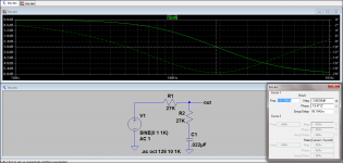
Actually the models are readily available and at some point I should be able to send them to you. Just PM me, in the mean time this should interest you. Noting also that as long as you make a reasonable estimate of the source Z you may not need to model the tube portion of the circuit. The -3dB point is ~190Hz as requested with resistor values that should be OK with 6DJ8 as a CF.. Lower transconductance types will have a higher source Z as CF which you can compensate for by adjusting the value of the first resistor in the network. What is most important is that the two channels match fairly closely, small errors can be trimmed by varying the value of the caps and resistors. I'm not sure that BSC is all that critical IMLE, but I have assumed that you need 6dB of BSC, if that is not the case then the resistor ratio changes to reflect that fact..
Attachments
Just for your interest, I built a BS compensation circuit in an active crossover a few years ago. This is based on Allen Wright's RTP3 and RTP5 circuitry, and works in differential mode. In the figure below, which is the high-pass section, the BS network is between the anodes of the input stage.Greetings,
I am building a tube preamp and it would be nice to roll in the baffle step compensation into the preamp circuit.
I have a 12AU7A on the preamp front end. I only need one half of the triode for each channel and I thought it would be good to employ that second triode, but I am unsure about the topology and circuit values.
My baffle is 2' wide, so my BSC F3 should be 190 Hz (380/2 feet = 190 Hz).
The OUT goes to the next stage in the preamp circuit.
I need to know:
1. Is the circuit topology valid?
2. What or better yet, how do I calculate the values for R6, R7, and C3?
Any other thoughts?
Thanks in advance!
An externally hosted image should be here but it was not working when we last tested it.
Note that I don't use this crossover these days: I decided that it was too complex (never mind too darn hot, with those fourteen 6922s!), and I had reliability problems in the low-pass section. The circuit I post here did actually work as designed, though.
Alex
Hi, I found, while playing on LTSpice, that messing whith R13/C3 figure on SY's RLD circuit, you can actually have a built-in BSC response, at least, on the simulator..
Would you be willing to share that simulation?
Bear in mind I do not have any spice tube data, so you would have to include those that you are using in with the schematic.
- Status
- This old topic is closed. If you want to reopen this topic, contact a moderator using the "Report Post" button.
- Home
- Amplifiers
- Tubes / Valves
- Baffle Step Compensation Tube Circuit