questions regarding 6c33c otl power supplies
I am building a pair of otl monoblocks based on another design. I have read this thread from the beginning and hope someone can advise me based on the experience gathered here. My power tubes need +170-0-170. Circuit calls for a very standard dual power supply using a 230vct with ct to ground, and a bridge rectifier to CRC filters.
I want to make use of transformers I have and change to a CLC filter. I find very little info on using 2 transformers for a dual power supply, but it seems it should be ok.
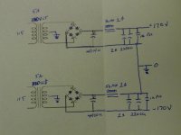
I have 2 x 130VCT 5A transformers. (overkill I know). Basically is there anything wrong with using one transformer for + rail and one for - using 2 bridge rectifiers. I would still attach the CT to ground to get the benefit of balanced supply to cancel common noise. I attach a diagram of my planned supply.
Excuse if this is too basic a question, but I want to get it right.
I am building a pair of otl monoblocks based on another design. I have read this thread from the beginning and hope someone can advise me based on the experience gathered here. My power tubes need +170-0-170. Circuit calls for a very standard dual power supply using a 230vct with ct to ground, and a bridge rectifier to CRC filters.
I want to make use of transformers I have and change to a CLC filter. I find very little info on using 2 transformers for a dual power supply, but it seems it should be ok.
I have 2 x 130VCT 5A transformers. (overkill I know). Basically is there anything wrong with using one transformer for + rail and one for - using 2 bridge rectifiers. I would still attach the CT to ground to get the benefit of balanced supply to cancel common noise. I attach a diagram of my planned supply.
Excuse if this is too basic a question, but I want to get it right.
Attachments
I am pretty certain that you have a problem with grounds.
You are grounding the center taps of the transformers AND you are grounding the junction of the two supplies. With their transformer center taps grounded, both circuits will provide a positive and a negative supply which is not what I think you were trying to achieve. With the junction of the supplies also grounded you will either blow fuses, or burn out components, or both.
The choke locations would be OK if the center taps weren't grounded since each supply can be considered separately - the choke in each case is in series, so it could go in the low voltage side or the high voltage side. There is an argument for putting the choke close to ground in terms of voltage since its insulation is subjected to lower voltage stresses (although for a decent choke it really should not matter).
I don´t know this exact circuit.
Many Otls use diffrent values for the bleeder resistor to create a bias voltage and then you need a single bridge solution.
One bridge is less voltage loss due to diode forwardvoltage and less switching noise.
I played around with chokes in my OTL, make sure the DCR are less then 0.5R.
Many Otls use diffrent values for the bleeder resistor to create a bias voltage and then you need a single bridge solution.
One bridge is less voltage loss due to diode forwardvoltage and less switching noise.
I played around with chokes in my OTL, make sure the DCR are less then 0.5R.
THanks!!! I am going to steal your design for stacking caps!!!
Me too! I like it! Thanks
Hi all,
Thought I'd add my 'twopennyworth' to the posts on the use of a non-centre tapped HT transformer.I made a couple of these Amps. one in Dec.2010 (6C41C) and the second (6C33C) in early 2011. (Both builds were posted on this site) Both are working well with no problems). As mentioned in my previous posts, I used ex-TV workshop Bench Isolation transformers (500W) in both designs. The only problem with this is that, because of the use of DC coupling,it is possible, that due to valve ageing or component drift (due to heat) the two halves of the channel become unbalanced. This may not show on the ammeter as this should show the current through the combined output stage - but, it may unbalance the 150v + & - rails, causing one rail to increase whilst the other decreases proportionally - this could of course cause damage to the ht smoothing capacitors particularly as they may not be rated for the combined ht voltage possible under these conditions. A simple insurance mod (!) (which I've done to both my amps, is to fit a 0-300v Voltmeter across one supply rail to ground. (Does,'t matter which) This then gives a visible indicatiion of any drifting of the ht voltages. The meter should normally read around half of the full rectified ht (300v or so). As a bonus, it makes balancing of the circuits vey easy as, with one stereo channel backed off (minimum current on the ammeter) the other channel balance can be set noting any movement from the correct voltage on the voltmeter. Then the standing current can be easily set. This channel is then backed off to enable the same proceedure to be used for the other channel.
Hope this makes sense (!) Having used this mod for a while it does make me feel happier that I should at least get an indication should unseen drifting occur.
Regards,
David (Nafunga)
Hi,
Its been a while since I did anything to the OTL amp I have just been listening to and enjoying it.
I have done away with the auto transformer and am only using the bench isolating transformer without center tap. I set up the offsets using my dvm and everything remained stable with no problems
...UNTIL...
My son had is 20th birthday party, and I noticed 2 of the 6c33 tubes glowing red! (it was playing very loud at the time but he bias was only at 150ma)
when I checked things out the next day I discovered that someone had tweaked the left hand Chanel offset pot and that the +/-150 volt rails wher 50 volts out i.e. +200 / -100 compared with the signal ground
Dave suggested above that a meter would be useful to monitor one of the rails constantly but as my build is complete I have no room for one, what I needed was some sort of zero volts detector that would show me whether the of-sett wad positive or negative
I have searched the web for ideas for an offset detector and found nothing of use so I designed this one from scratch
circuit attached
Attachments
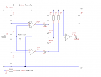
The two 4k7 resistors drop the 150v rails down to 15v this gives me a board rail of 30 volts across the 200uf 63v (the lM339 is rated to work at this voltage) this is then divided by the three 1k resistors, the top and bottom of the middle resistor will be at +5 /-5 volts relative to ground if there is no offset.
Feeding the top point of the center resistor into the non inverting input of a comparator lights a green led when the offset is +5v or more and Feeding the bottom point of the centre resistor into the inverting input of a comparator will lights a red led when the offset is -5v or more.
D1 and 2 form a nand gate so that if both other led's are off an orange led will be alight.
So when the offset is ok (within +-5v) I can see the comforting orange glow projected on the wall behind the amp.
6c33 overheated due to wrong off-set
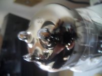
just as a footnote = a picture of one of the overheated tubes
these 6c33 tubes really are rugged once burnt in properly,
despite this tube glowing cherry red when being over run (to the extent that the getter deposits on the inside of the glass are burnt) the tube still works ok and the bias sets up the same as a one of the other tubes when I swap them around.
I really trust Tim's design 100% and 9 months on the lesson learned is that the off sett pots do not need to be easily accessible. you could get away with having the bias pots hidden too but. the benefits are that as you crank up the bias the damn thing just sounds even better")
just as a footnote = a picture of one of the overheated tubes
these 6c33 tubes really are rugged once burnt in properly,
despite this tube glowing cherry red when being over run (to the extent that the getter deposits on the inside of the glass are burnt) the tube still works ok and the bias sets up the same as a one of the other tubes when I swap them around.
I really trust Tim's design 100% and 9 months on the lesson learned is that the off sett pots do not need to be easily accessible. you could get away with having the bias pots hidden too but. the benefits are that as you crank up the bias the damn thing just sounds even better
Attachments
I have the multiturn trimmers hidden under the topplate so the drilled hole guide the screwdriver.
One DVM atached to 2 panel jacks connected to a 0.1 resistor to check dissipation and a another DVM attached to speaker posts to check offset.
That´s all it takes to adjust my OTL.
And agree with your experience ones they settle they are very stable and takes lots of abuse.
One DVM atached to 2 panel jacks connected to a 0.1 resistor to check dissipation and a another DVM attached to speaker posts to check offset.
That´s all it takes to adjust my OTL.
And agree with your experience ones they settle they are very stable and takes lots of abuse.
re power supply
FYI, built the power supply and it works perfectly. Per discussion here, no CT to ground and all is well.
I am building a pair of otl monoblocks based on another design. I have read this thread from the beginning and hope someone can advise me based on the experience gathered here. My power tubes need +170-0-170. Circuit calls for a very standard dual power supply using a 230vct with ct to ground, and a bridge rectifier to CRC filters. ...
FYI, built the power supply and it works perfectly. Per discussion here, no CT to ground and all is well.
Voltages marked on Fig 1 of feb2010 audioxpress is strange. While the HT is +-350150 and -150,
the voltage at the junction of v2 and v3 is marked -350v ??
at grid of v5 -200 ??
at grid of v4 -50 ??
Would someone share the measured values please.
The voltages are about right. The voltage at the cathodes of V2 and V3 should be just a few volts positive of their g1 grids. The voltage on the g1 grids is set by the voltage divider composed of R8 and R10 (and also R9 and R11), with the R8 far-end at +100V and the R10 far-end at -430V. With R8= 4.7M and R10= 1.0M, that would means g1 is at about -337V. So maybe that -350V indicated in the schematic is a bit off, but only by 15V or so.
As for the grids of V4 and V5, the biasing for 200mA or so of anode current in the 6C33C requires that the grid should be at about -50V relative to the cathode. Hence -50V for V4, since its cathode is at 0V, and -200V for V5, since its cathode is at -150V.
I measured on mine, and those figures are in the same ballpark as indicated in the schematic.
Chris
Hi!
I would like to ask some questions about the PSU:
For only one channel (in a dual mono amplifier)
- how big transformers need I? For the power tubes 250VA? For 6C33C heater 100VA and for the driving tubes 15VA enough?
- should the R33 1K be 5W?
- should the FS1 and FS2 fuses be 1.5A?
- instead of the amp meters 0.1Ohm power resistor"s wattage?
Greets:
Tyimo
- Home
- Amplifiers
- Tubes / Valves
- New Tim Mellows OTL project