Progress!
Hi,
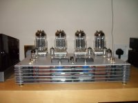
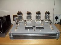
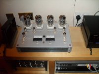
I have been so busy listening to the new amp I have not had much time to post anything.. so here are of a few more pictures of the amp
I can't say its finished yet, but its all wired up and working and sounding fantastic.
I intend to wait till its run in a bit longer before turning it up really loud, and so far I am running the bias at 150ma Maximum.
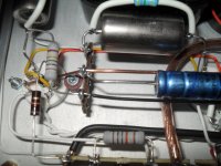
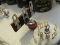
I have wired the the heaters to the first stage via a jumper tag so that I can swap to my Mullard ECC83's quickly for a comparison test, not sure weather you can see this in the detail in the pictures posted already, if not I will post a close up.
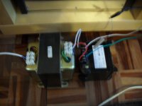
The mid point voltage has settled down to within a few volts using my "auto transformer centre tap but I still intend to try my resistor centre tap idea to save having two HT transformers.
Tony.
Hi,
I have been so busy listening to the new amp I have not had much time to post anything.. so here are of a few more pictures of the amp
I can't say its finished yet, but its all wired up and working and sounding fantastic.
I intend to wait till its run in a bit longer before turning it up really loud, and so far I am running the bias at 150ma Maximum.
I have wired the the heaters to the first stage via a jumper tag so that I can swap to my Mullard ECC83's quickly for a comparison test, not sure weather you can see this in the detail in the pictures posted already, if not I will post a close up.
The mid point voltage has settled down to within a few volts using my "auto transformer centre tap but I still intend to try my resistor centre tap idea to save having two HT transformers.
Tony.
Attachments
")
Τhanks for the answer Tony .Hi,
The 2w 500v metal resistors in the picture above came from my local Maplin shop, they do have an on line catalogue@ maplin.co.uk but Im not sure if they post to Greece...
I could bring some across to you (if you pay my air fare)
Cheers,
Tony.
And somtheng else , I think it would be better in the power supply to use one single capacitor in each rail instead the series connected capacitors C8 to C 15 .
Hi,
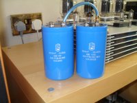
if you check post #59 I have redrawn Tims circuit to to show that these caps are in the loudspeaker signal path hence I have used Samwah gold audio grade caps (as specified by Tim Mellows in his original article) these are stacked to give the required voltage.
single audio grade HT caps such as Black gate etc. are harder to get hold of and would be much more expensive.
p.s. listening to the amp at the moment... sounds better every day.
Tony.
Cheers
I know that those capacitors is in the loudspeaker signal path ( the amp is OTL but not OCL ) , and when they are connected in series they have much higher ESR and then the amp have higher output impedance , so IMO if one ( on each rail ) capacitor is there with low ESR then the output impedance will be lower .Hi,
if you check post #59 I have redrawn Tims circuit to to show that these caps are in the loudspeaker signal path hence I have used Samwah gold audio grade caps (as specified by Tim Mellows in his original article) these are stacked to give the required voltage.
single audio grade HT caps such as Black gate etc. are harder to get hold of and would be much more expensive.
p.s. listening to the amp at the moment... sounds better every day.
Tony.
Cheers
It's not out of topic but I have built an OTL amp Futterman topology with 12 PL36 on each channel ( since 2004 ) and the center tap of the transformer is connected directly to the capacitors , with this way the capacitors aren't in the loudspeaker path because they are simply power supply capacitors .
Maby one of the reasons they connected like this in Tim's amp is to reduce the inrush current when the amp switched on .
Last edited:
I know that those capacitors is in the loudspeaker signal path ( the amp is OTL but not OCL ) , and when they are connected in series they have much higher ESR and then the amp have higher output impedance , so IMO if one ( on each rail ) capacitor is there with low ESR then the output impedance will be lower .
It's not out of topic but I have built an OTL amp Futterman topology with 12 PL36 on each channel ( since 2004 ) and the center tap of the transformer is connected directly to the capacitors , with this way the capacitors aren't in the loudspeaker path because they are simply power supply capacitors .
Maby one of the reasons they connected like this in Tim's amp is to reduce the inrush current when the amp switched on .
I don't think there is really any distinction between the two cases (centre-tap of transformer connected to capacitors or not), as far as the audio path is concerned. If you trace the audio signal current, it always goes through the speaker, tubes and power supply. In the power supply, it necessarily goes through the capacitors (since otherwise it could only instead pass through the rectifiers and power transformer secondary windings).
Chris
No I disagree with you , there is a significant difference between the two cases , If you don't connect the centre tap of the transformer directly onto the capacitors ( in this way the power supply called floating earth power supply ) then the two capacitors will charged from the power supply from the positive pole of the upper and the negative pole of the lower because they are in series , and the charge of the one is depended from the other because they are in series too , but if you connect the centre tap then you have two power supplies ( e.g. +150V 0 -150V ) just like transistor circuits , and each capacitor will be charged from it's own power supply when it get disarghed .I don't think there is really any distinction between the two cases (centre-tap of transformer connected to capacitors or not), as far as the audio path is concerned. If you trace the audio signal current, it always goes through the speaker, tubes and power supply. In the power supply, it necessarily goes through the capacitors (since otherwise it could only instead pass through the rectifiers and power transformer secondary windings).
Chris
Αs for the audio signal current I agree with you because it's transparently obvious .
Last edited:
No I disagree with you , there is a significant difference between the two cases , If you don't connect the centre tap of the transformer directly onto the capacitors ( in this way the power supply called floating earth power supply ) then the two capacitors will charged from the power supply from the positive pole of the upper and the negative pole of the lower because they are in series , and the charge of the one is depended from the other because they are in series too , but if you connect the centre tap then you have two power supplies ( e.g. +150V 0 -150V ) just like transistor circuits , and each capacitor will be charged from it's own power supply when it get disarghed .
Αs for the audio signal current I agree with you because it's transparently obvious .
My comment was only concerned with whether the capacitors are "in the loudspeaker path." I took those words to mean "in the audio signal path." If you agree that this is essentially unchanged regardless of whether the centre-tap is connected or not, then we are in agreement.
Chris
The capacitors in case of the connected centre tap is acting like any other capacitors of power supplies ( in the signal path ) , but in case of the non connected centre tap the capacitors is acting like output capacitors , but instead one we have two , I hope you understand my point of view .My comment was only concerned with whether the capacitors are "in the loudspeaker path." I took those words to mean "in the audio signal path." If you agree that this is essentially unchanged regardless of whether the centre-tap is connected or not, then we are in agreement.
Chris
The capacitors in case of the connected centre tap is acting like any other capacitors of power supplies ( in the signal path ) , but in case of the non connected centre tap the capacitors is acting like output capacitors , but instead one we have two , I hope you understand my point of view .
I think the capacitors are just as much "acting like output capacitors," as far as the audio signal path is concerned, if the centre-tap is connected or if it is not connected.
If this were not true, then it would have to mean that if one had the amplifier running without the centre-tap connected, and then on connected up the centre-tap while the amplifier was in operation, then the audio signal would "re-route" through the power supply transformer (and the rectifiers) via its centre-tap. Since the secondary winding has appreciable inductance, it would seem clear that no significance audio signal could route through it. And I think one would certainly hope that the audio signal path was not routing through the power transformer and rectifiers!
Thus, I think it is the case that the audio signal is, to all intents and purposes, going purely through the capacitors, regardless of whether the centre-tap is connected or not. In particular, it is equally important in either case that the capacitors should be capable of passing the audio signal without significant degradation.
In each case, one is relying on the power-supply capacitors to behave like more-or-less a "short-ciruit," or in other words to make the power supply like a more-or-less ideal "battery," at audio frequencies. The extent to which they actually achieve this is dependent on the audio signal handling capabilities of the capacitors.
Although you may choose to use different words in the two cases, the fact is that the audio signal is following essentially the identical route regardless of whether the centre-tap is connected or not.
Chris
Last edited:
I think the capacitors are just as much "acting like output capacitors," as far as the audio signal path is concerned, if the centre-tap is connected or if it is not connected.
If this were not true, then it would have to mean that if one had the amplifier running without the centre-tap connected, and then on connected up the centre-tap while the amplifier was in operation, then the audio signal would "re-route" through the power supply transformer (and the rectifiers) via its centre-tap. Since the secondary winding has appreciable inductance, it would seem clear that no significance audio signal could route through it. And I think one would certainly hope that the audio signal path was not routing through the power transformer and rectifiers!
Thus, I think it is the case that the audio signal is, to all intents and purposes, going purely through the capacitors, regardless of whether the centre-tap is connected or not. In particular, it is equally important in either case that the capacitors should be capable of passing the audio signal without significant degradation.
In each case, one is relying on the power-supply capacitors to behave like more-or-less a "short-ciruit," or in other words to make the power supply like a more-or-less ideal "battery," at audio frequencies. The extent to which they actually achieve this is dependent on the audio signal handling capabilities of the capacitors.
Chris
Well , it's not like this , for example we have two capacitors say 2200μF / 250V and a 4 diode ( bridge ) rectifier and two secondary windings with a centre tap .
If the centre tap is connected , then we have two full wave rectified power supplies say +150V 0 and -150V , when the amp is playing in high levels then this audio signal current create a voltage drop alternately on those capacitors ( depending on which tube is acting ) and as the voltage let say on the upper capacitor start to fall the power supply will charge it immediately via the two diodes and the centre tap ( in this case the two windings is in "parallel" connection ) and in case that the capacitor have high ESR then this voltage drop will be higher than that on a capacitor with low ESR .
Without the centre tap the charge of the upper capacitor will depented from the 4 diodes and the two secondary windings which now is in series connection plus the lower capacitor ( and it's ESR ) , the same thing happens when the lower capacitor discharged , and if those capacitors have high ESR then the things is getting worse .
Last edited:
Well , it's not like this , for example we have two capacitors say 2200μF / 250V and a 4 diode ( bridge ) rectifier and two secondary windings with a centre tap .
If the centre tap is connected , then we have two full wave rectified power supplies say +150V 0 and -150V , when the amp is playing in high levels then this audio signal current create a voltage drop alternately on those capacitors ( depending on which tube is acting ) and as the voltage let say on the upper capacitor start to fall the power supply will charge it immediately via the two diodes and the centre tap ( in this case the two windings is in "parallel" connection ) and in case that the capacitor have high ESR then this voltage drop will be higher than that on a capacitor with low ESR .
Without the centre tap the charge of the upper capacitor will depented from the 4 diodes and the two secondary windings which now is in series connection plus the lower capacitor ( and it's ESR ) , the same thing happens when the lower capacitor discharged , and if those capacitors have high ESR then the things is getting worse .
Well, this is quite an involved question. Suppose the audio signal is a very high level 1KHz sinewave. You are, I think, discussing the voltage fall across the upper capacitor during the 500 microseconds of the relevant half-cycle of the sinewave. I don't think you can say that the capacitor will necessarily be recharged "immediately" by the power supply, since for much of the cycle of the much lower frequency sinewave of the 60Hz or 50Hz mains supply, the voltage will be insufficient to exceed the (slightly depleted) capacitor voltage, and so during that particular half cycle of the 1KHz audio signal, the capacitor might not get recharged at all.
I think, though, that this point you raised is in any case a little bit of a side issue, and a rather complicated one also. If we stick to considering small-signal conditions, then I suspect you and I would agree that the audio signal follows essentially the same path, independently of whether the centre-tap is connected or not.
Chris
Good Morning Gents,
Interesting discussion.
Having spent around a year searching for a more powerful valve amp since finishing my Mullard 3-3 stereo version.
I had decided on and then rejected several designs including 300b se's, pl509 otl's (as I have 4 of these tubes)and finaly Andrea Ciufoli's simple otl (thats what got me interested in 300b's)
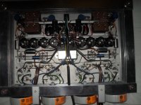
When I decided on Tims design it was "a leap of faith" so I have followed his article as closey as posible as regards component types, Plus as I wanted a slim style with no big transformers and caps sticking out of the top the 8 seperate caps fitted the bill here too.
In my layout I have arranged my caps with the earth at the outside edges( to keep the high voltage psu parts away from the signal stage) so I could quickly disconnect the two earth busbars and tap in a couple of the 1000uf 450v caps that I have in stock and then do a listening test,
what do you think?
Tony.
Interesting discussion.
Having spent around a year searching for a more powerful valve amp since finishing my Mullard 3-3 stereo version.
I had decided on and then rejected several designs including 300b se's, pl509 otl's (as I have 4 of these tubes)and finaly Andrea Ciufoli's simple otl (thats what got me interested in 300b's)
When I decided on Tims design it was "a leap of faith" so I have followed his article as closey as posible as regards component types, Plus as I wanted a slim style with no big transformers and caps sticking out of the top the 8 seperate caps fitted the bill here too.
In my layout I have arranged my caps with the earth at the outside edges( to keep the high voltage psu parts away from the signal stage) so I could quickly disconnect the two earth busbars and tap in a couple of the 1000uf 450v caps that I have in stock and then do a listening test,
what do you think?
Tony.
Attachments
The audio output signal is the product of the power supply voltage "modulated" or "shaped" by the output tubes and delivered to the speakers , so you can't ignore the importance of a good quality power supply voltage in an amplifier only by speaking about the audio signal path .Well, this is quite an involved question. Suppose the audio signal is a very high level 1KHz sinewave. You are, I think, discussing the voltage fall across the upper capacitor during the 500 microseconds of the relevant half-cycle of the sinewave. I don't think you can say that the capacitor will necessarily be recharged "immediately" by the power supply, since for much of the cycle of the much lower frequency sinewave of the 60Hz or 50Hz mains supply, the voltage will be insufficient to exceed the (slightly depleted) capacitor voltage, and so during that particular half cycle of the 1KHz audio signal, the capacitor might not get recharged at all.
I think, though, that this point you raised is in any case a little bit of a side issue, and a rather complicated one also. If we stick to considering small-signal conditions, then I suspect you and I would agree that the audio signal follows essentially the same path, independently of whether the centre-tap is connected or not.
Chris
And something else , if we disconnect the centre tap of the power supply in an transistor amplifier , would this amplifier sounds the same and deliver the same power to the speakers ? definitely not , the same thing happens in an tube amp. which has a similar power supply .
The audio output signal is the product of the power supply voltage "modulated" or "shaped" by the output tubes and delivered to the speakers , so you can't ignore the importance of a good quality power supply voltage in an amplifier only by speaking about the audio signal path .
I think then we are in complete agreement; there is more to a power supply than just the audio signal path. My previous comments were specifically addressing the restricted question of the audio path, and I was pointing out that regardless of the centre-tap connection or not, the capacitors are part of the audio signal path.
By the way, I am a great fan of OTL amps, and have built three of them, using the designs of Hans Beijner, Tim Mellow and Alan Kimmel.
Chris
- Home
- Amplifiers
- Tubes / Valves
- New Tim Mellows OTL project