Hi,
Already have high melting point solder ready and waiting.
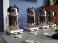
I have burned output tubes for 5 hours each heaters only, I will then run up amp for a couple of hours with bias pot at minimum (hopefully 100ma or so).
Only have 4 of these tubes so not a lot of choice with pairing.
Hi precision resistors are by Welwyn.
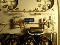
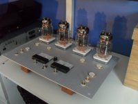
Progress today.. LHC driver wiring completed, doing the other channel should be a lot quicker now I have worked out the layout.
n.b. tagstrip at back goes straight to the triodes of 6c33s... so not a lot more to do just routing of PSU rails and connection to bias pot centre
Already have high melting point solder ready and waiting.
I have burned output tubes for 5 hours each heaters only, I will then run up amp for a couple of hours with bias pot at minimum (hopefully 100ma or so).
Only have 4 of these tubes so not a lot of choice with pairing.
Hi precision resistors are by Welwyn.
Progress today.. LHC driver wiring completed, doing the other channel should be a lot quicker now I have worked out the layout.
n.b. tagstrip at back goes straight to the triodes of 6c33s... so not a lot more to do just routing of PSU rails and connection to bias pot centre
Attachments
Hi Smith, are you building straight from Tim's original scheem? I just found enough copper plate to make both my chassis and want to start this build as soon as I finish two others. I am looking for 2 meters for this and would like them to be old style round no bigger than 2 inches across. Any idea where I might find them? D.
Hi, D
I am working from Tims article published in Audio Xpress magazine 2/10
(N.B. the March 2012 edition is now available on-line.... just Google it.)
The only changes that I have made are to up rate C18 to 500v (as it must have at least 280v across it) plus I am using 500ma meters and I have only included one fuse, the one in the +150 supply.
Apart from my choice of input and coupling capacitors the circuit and the rest of the components are as per Tims spec.
Please can you explain what you are looking for I don,t understand what you mean "old style round 2 inches across" ?
Last edited:
Hi,
Already have high melting point solder ready and waiting.
I have burned output tubes for 5 hours each heaters only, I will then run up amp for a couple of hours with bias pot at minimum (hopefully 100ma or so).
Only have 4 of these tubes so not a lot of choice with pairing.
Hi precision resistors are by Welwyn.
Progress today.. LHC driver wiring completed, doing the other channel should be a lot quicker now I have worked out the layout.
n.b. tagstrip at back goes straight to the triodes of 6c33s... so not a lot more to do just routing of PSU rails and connection to bias pot centre
You know,
I don't think 5 Hrs with heater will cut it..you may get away with it, I was told not less than 12hrs ie a whole day heaters only no bias..(this was supposed to be taking a risk)
Then let them cool and give it another couple of hours..before any B+ or low bias..
If it hasen't been enough they will flash over and their history..
")
The tubes are supposed to expand during this time and settle into a running position.
Regards
M. Gregg
Last edited:
Hi, D
I am working from Tims article published in Audio Xpress magazine 2/10
(N.B. the March 2012 edition is now available on-line.... just Google it.)
The only changes that I have made are to up rate C18 to 500v (as it must have at least 280v across it) plus I am using 500ma meters and I have only included one fuse, the one in the +150 supply.
Apart from my choice of input and coupling capacitors the circuit and the rest of the components are as per Tims spec.
Please can you explain what you are looking for I don,t understand what you mean "old style round 2 inches across" ?
Just a quick question,
Only one fuse in the +150?
I thought that the CT of the Tx would give you a short through the bottom tube if it goes short? and stuff the speaker?
Regards
M. Gregg
Thanks Smith. I am making the two chassis out of copper and would like to find old brass round meters. Just to complete the look.
Hi, D
I am working from Tims article published in Audio Xpress magazine 2/10
(N.B. the March 2012 edition is now available on-line.... just Google it.)
The only changes that I have made are to up rate C18 to 500v (as it must have at least 280v across it) plus I am using 500ma meters and I have only included one fuse, the one in the +150 supply.
Apart from my choice of input and coupling capacitors the circuit and the rest of the components are as per Tims spec.
Please can you explain what you are looking for I don,t understand what you mean "old style round 2 inches across" ?
Hi, M Gregg
Thanks for the feedback I will burn the 6c33's for a few more hours each.
In Tims design the the centre tap is connected through a 1k resistor for stabilisation purposes only. if the + 150v fuse fails all the voltages will drop as this this is the top feed to a capacitive divider, the -150 rail is effectively the "ground" point so
it should be O.K. with one fuse.
The following is copied from the article by Tim ;-
"Fuses F1 and F2 are provided in the unlikely event that both driver tubes, V2
and V3, fail (or not being plugged in),thus causing an excessive current to flow
through both output tubes V4 and V5. In theory, only one fuse is needed, but
two are included here in order that any non linearity they produce is symmetrical"
On my panel layout I have allowed for one fuse in the middle, I have a good ear, but I cant hear the difference that a fuse makes to a circuit.
Tony.
further to the whole fuse centre tap thing,
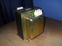
I forgot to mention previously that I am using a 500w mains isolation transformer with no centre tap, this has been done before.. one guy has built two of them,one for himself and then one for his son.
if stabilisation is a problem then 2 x 1k 15w resistors forming a potential divider across the transformer would have the same effect as Tims 1k to the CT.
The 30w dissipation would be a problem for most designs but I would not have an issue with this as they could be placed with the transformer and help to heat heat the rest of the room.
Tony.
further to the whole fuse centre tap thing,
I forgot to mention previously that I am using a 500w mains isolation transformer with no centre tap, this has been done before.. one guy has built two of them,one for himself and then one for his son.
if stabilisation is a problem then 2 x 1k 15w resistors forming a potential divider across the transformer would have the same effect as Tims 1k to the CT.
The 30w dissipation would be a problem for most designs but I would not have an issue with this as they could be placed with the transformer and help to heat heat the rest of the room.
Tony.
Hi,
300V \2K..0.15 *300?
Whats wrong with 2X 10K or 15K or 20K? Wire wound non inductive?
If you have no CT I would think that a divider was important.
You might get an off set between CP and each side..speaker returns to CP?
Regards
M. Gregg
I still think,
If the bottom half of your capacitor bank discharges through the speaker coil if the bottom tube goes short it will blow the speaker coil like a fuse.
Your choice, that negative rail fuse looks very interesting..
I bonded my CP with 2.5 to Earth to make sure the speaker was grounded and earthed. Each to his own I guess..
Regards
M. Gregg
Is there anything special about the B+ power supply??? I have a PS that I can turn down to what is called for in the schematic but don't know if there is any in the stated PS that is particular to this amp.
There are people on here that can answer you better than I can,
However the PSU is very important, the bass reproduction and sound stage etc.
The B+ is part of a balanced +/- PSU I would think the capacitor types used would have to be the same and the ESR. The CT on the Tx when removed on my amp the bass reduces. The PSU is the Heart of this amp.
Without a CT Tx a psudo CT is needed to keep the PSU balanced. This is obviously at gnd and earth. Hum rejection is also helped.
I must add my amp is not a Tim Mellow however the same rules apply with the futterman and 6C33C's
Regards
M. Gregg
Last edited:
Good morning,
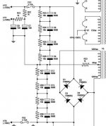
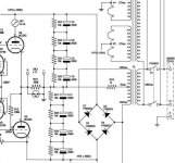
I have posted a section from Tims circuit and then my idea for a virtual centre tap, the two resistors are across the AC side of the bridge hence the need for 30w (2 x 15w wirewound)
Below is Tims explanation of the circuit:-
POWER SUPPLY
Although the power supply is fairly
conventional (Fig. 3) and therefore in
little need of description, there are a few
points worthy of note: In the event of a
fault forcing the output stage latch either
up or down, R33 provides a means
of limiting the current through the output
stage and loudspeaker. If its value
were too small, either an output tube or
the loudspeaker or both could be damaged.
If its value were too high, a small
offset voltage across the loudspeaker
could cause a significant imbalance in
the supply voltages HT2 and HT4.
So from what I've read, the offset on this amp is stable and does not drift once set-up, I will try it without the resistors first and add them later if required.
I have suggested 1k for the resistors but I would do a trail and increase them gradually and then test for stability to find the best compromise.
From reading Tims text.. The higher the better.
Tony.
Attachments
Good morning,
I have posted a section from Tims circuit and then my idea for a virtual centre tap, the two resistors are across the AC side of the bridge hence the need for 30w (2 x 15w wirewound)
Below is Tims explanation of the circuit:-
POWER SUPPLY
Although the power supply is fairly
conventional (Fig. 3) and therefore in
little need of description, there are a few
points worthy of note: In the event of a
fault forcing the output stage latch either
up or down, R33 provides a means
of limiting the current through the output
stage and loudspeaker. If its value
were too small, either an output tube or
the loudspeaker or both could be damaged.
If its value were too high, a small
offset voltage across the loudspeaker
could cause a significant imbalance in
the supply voltages HT2 and HT4.
So from what I've read, the offset on this amp is stable and does not drift once set-up, I will try it without the resistors first and add them later if required.
I have suggested 1k for the resistors but I would do a trail and increase them gradually and then test for stability to find the best compromise.
From reading Tims text.. The higher the better.
Tony.
I think if you do it on the DC side or AC as shown then 10K 12Watt (Dissipation about 4.5W) would be fine, it works on non CT PSU's on the DC side. Without the CT you are relying on the resistors across the caps in the PSU to keep it stable. Cp on the caps is ref to Gnd /Earth and speaker return.
You still have charged caps across the speaker via the CP and bottom tube, the resistor value R33 you refer to is irrelevant under capacitor short conditions with bottom tube flash over. I touched one of my rails down by accident to gnd and blew a 2mm hole through a 3mm aluminium plate. The PSU was off but had not completly discharged. (I was testing for dead) So there was no AC on the circuit. The -rail fuse blew and the caps were still up for a few seconds. ( I still think without a - rail fuse you could get a nasty surprise)..again YMMV
If you don't like the Idea of fuses and sound then you can bypass the fuse on a DC rail with a very low value polypropylene cap high voltage. The cap will bypass the fuse link ac and block the DC on fuse OC.
These are only thoughts YMMV.
I'll shut up now and let you build..LOL
Regards
M. Gregg
Last edited:
Hi,
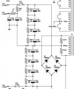
I have redrawn Tims circuit to show that the PSU caps are part of the output stage ( hence the need for Samwa gold caps specified by him ) this gives a clearer picture of how his circuit works.
You can see that the earth ground to the speakers has no effect on the DC in the OP stage as it is connected to the other side of the isolating transformer, only the 1k goes to the centre point. to me this suggests that my divider idea will work o.k.
having studied the circuit in this form I think I agree with you about the fuse I will fit a fuse on the -150v rail somewhere under the chassis, to be fair I only fitted the fuse holder on the top panel for aesthetic reasons
A BIG Thanks for your help, you may well have saved me form an expensive mistake.
Nb I am having a rest from building today..
I am going to set up the tubes for a longer burn and as my tube bases are already mounted, I cant work on the project.
Thanks again for your help !
I have redrawn Tims circuit to show that the PSU caps are part of the output stage ( hence the need for Samwa gold caps specified by him ) this gives a clearer picture of how his circuit works.
You can see that the earth ground to the speakers has no effect on the DC in the OP stage as it is connected to the other side of the isolating transformer, only the 1k goes to the centre point. to me this suggests that my divider idea will work o.k.
having studied the circuit in this form I think I agree with you about the fuse
I will fit a fuse on the -150v rail somewhere under the chassis, to be fair I only fitted the fuse holder on the top panel for aesthetic reasonsA BIG Thanks for your help, you may well have saved me form an expensive mistake.
Nb I am having a rest from building today..
I am going to set up the tubes for a longer burn and as my tube bases are already mounted, I cant work on the project.
Thanks again for your help !
Attachments
- Home
- Amplifiers
- Tubes / Valves
- New Tim Mellows OTL project