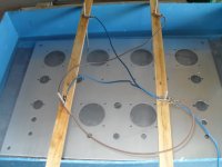
Anodising the top panel
on my first attempt I tried unsuccessfully to seal the top panel in a steam box, I have tried a few test pieces and get better results boiling in de ionised water....
I just need to get a pan large enough to take a 300mm x 430mm panel.
on my first attempt I tried unsuccessfully to seal the top panel in a steam box, I have tried a few test pieces and get better results boiling in de ionised water....
I just need to get a pan large enough to take a 300mm x 430mm panel.
Attachments
on my first attempt I tried unsuccessfully to seal the top panel in a steam box, I have tried a few test pieces and get better results boiling in de ionised water....
I just need to get a pan large enough to take a 300mm x 430mm panel.
This is interesting...
Please give full info of how you are anodising ..chemicals and type of power and currents etc..just for fun of course..
")
What colour are you going to use?
On my visits to anodising the vats were open and heated to a specific temp. Coveyor feed...It is possible to burn the aluminium and get a speckled effect (over current)<<not good..
Regards
M. Gregg
Last edited:
Hi,
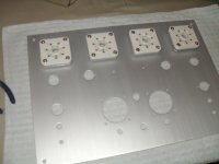
I am using sodiumbisulphate as the electrolite instead of the usual nasty sulphuric acid (this is used to lower the ph in swimming pools) so far with good results on small samples.
I have done a test on a small plate using yellow printer ink as the dye to test and this worked well but for my amp I want silver.
as for the current most on line diy info suggests 12 amps per square foot per hour with a max current of 6A to avoid overheating thus at max curent taking 2 hours to anodise.
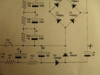
. I have built a variable psu for testing but I used a car battery charger with a 10000 uf cap for the large top plate.
I am using sodiumbisulphate as the electrolite instead of the usual nasty sulphuric acid (this is used to lower the ph in swimming pools) so far with good results on small samples.
I have done a test on a small plate using yellow printer ink as the dye to test and this worked well but for my amp I want silver.
as for the current most on line diy info suggests 12 amps per square foot per hour with a max current of 6A to avoid overheating thus at max curent taking 2 hours to anodise.
. I have built a variable psu for testing but I used a car battery charger with a 10000 uf cap for the large top plate.
Very interesting!
Hi,
This sounds very interesting! Would it be possible for you to open a new topic and describe the proces that you are using to anodize aluminum? I think allot of diy members (like myself) could benefit from knowing this information
Hi,
I am using sodiumbisulphate as the electrolite instead of the usual nasty sulphuric acid (this is used to lower the ph in swimming pools) so far with good results on small samples.
I have done a test on a small plate using yellow printer ink as the dye to test and this worked well but for my amp I want silver.
as for the current most on line diy info suggests 12 amps per square foot per hour with a max current of 6A to avoid overheating thus at max curent taking 2 hours to anodise.
. I have built a variable psu for testing but I used a car battery charger with a 10000 uf cap for the large top plate.
Hi,
This sounds very interesting! Would it be possible for you to open a new topic and describe the proces that you are using to anodize aluminum? I think allot of diy members (like myself) could benefit from knowing this information
Hi,
This sounds very interesting! Would it be possible for you to open a new topic and describe the proces that you are using to anodize aluminum? I think allot of diy members (like myself) could benefit from knowing this information
Yes please create a DIY anodising for dummies thread...
This sounds like I'm joking but I'm not..This would be brilliant for the DIY forum..
A few diagrams of the circuit and setup would be great...perhaps a few photos of your anodised parts and progress..Well with printer ink there are a few coulours
Magenta, Blue, Black, Cyan, it goes on..
Regards
M. Gregg
Last edited:
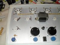
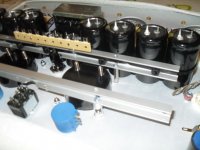
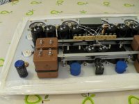
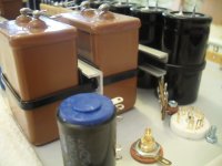
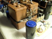
Finished fitting rails for all the caps ( 2 more 100/250 to find a home for )
notice the protection around the panel ...I have promised myself not to drop or dent this one while working on it
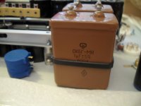
I have just managed to squeeze in big fat Russian PIO caps ,the panel is standard 430 x 300 (17x12) hi-fi size but still seems quite full, I don't know how Tim managed to fit it all in to his 12 x 9 inch chassis.
Well back to work... soon be time to fire up the soldering iron
notice the protection around the panel ...I have promised myself not to drop or dent this one while working on it
I have just managed to squeeze in big fat Russian PIO caps ,the panel is standard 430 x 300 (17x12) hi-fi size but still seems quite full, I don't know how Tim managed to fit it all in to his 12 x 9 inch chassis.
Well back to work... soon be time to fire up the soldering iron
Attachments
Hi all,
Thanks for you comments,
I have spent hours pouring over the layout and the best way to fit it all together...
All the tubes and are to be Russian + the 0.1uf and 1uf in the audio path I have used paper in oil caps as most audio forums seem to rate them. When testing the Russian ef86 tubes in my Mullard 3-3 amp and they sounded good and perhaps slightly cleaner than the Mullards.
I will by trying both ecc83's and 6n2p's in the first stage during testing.. hopefully the Russian tubes will impress as I use the mullards in my Aikido based headphone amp.
and only have 1 spare + more made by 1 by pinnacle..
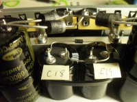
note the stickers to remind me while wiring ...diodes and cap all ways round in the -430 supply
more pics to follow in a few days.. have to go to work
Thanks for you comments,
I have spent hours pouring over the layout and the best way to fit it all together...
All the tubes and are to be Russian + the 0.1uf and 1uf in the audio path I have used paper in oil caps as most audio forums seem to rate them. When testing the Russian ef86 tubes in my Mullard 3-3 amp and they sounded good and perhaps slightly cleaner than the Mullards.
I will by trying both ecc83's and 6n2p's in the first stage during testing.. hopefully the Russian tubes will impress as I use the mullards in my Aikido based headphone amp.
and only have 1 spare + more made by 1 by pinnacle..
note the stickers to remind me while wiring ...diodes and cap all ways round in the -430 supply
more pics to follow in a few days.. have to go to work
Attachments
Hi all,
Thanks for you comments,
I have spent hours pouring over the layout and the best way to fit it all together...
All the tubes and are to be Russian + the 0.1uf and 1uf in the audio path I have used paper in oil caps as most audio forums seem to rate them. When testing the Russian ef86 tubes in my Mullard 3-3 amp and they sounded good and perhaps slightly cleaner than the Mullards.
I will by trying both ecc83's and 6n2p's in the first stage during testing.. hopefully the Russian tubes will impress as I use the mullards in my Aikido based headphone amp.
and only have 1 spare + more made by 1 by pinnacle..
note the stickers to remind me while wiring ...diodes and cap all ways round in the -430 supply
more pics to follow in a few days.. have to go to work
Hi,
A few thoughts for what they are worth..
Your diodes should be sleeved the current and power stored in the PSU should not be under estimated.
Do you know how hot these tubes run? Think cooker element.
The mains power is also quite high..this may not matter, however at least you know..
Regards
M. Gregg
Hi all,
Thanks for you comments,
I have spent hours pouring over the layout and the best way to fit it all together...
All the tubes and are to be Russian + the 0.1uf and 1uf in the audio path I have used paper in oil caps as most audio forums seem to rate them. When testing the Russian ef86 tubes in my Mullard 3-3 amp and they sounded good and perhaps slightly cleaner than the Mullards.
I will by trying both ecc83's and 6n2p's in the first stage during testing.. hopefully the Russian tubes will impress as I use the mullards in my Aikido based headphone amp.
and only have 1 spare + more made by 1 by pinnacle..
note the stickers to remind me while wiring ...diodes and cap all ways round in the -430 supply
more pics to follow in a few days.. have to go to work
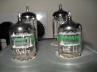
Hello ! I check this type caps(on photo) on Russian forum that tru this one PIO but I have another type . MBGO(It seems like yorth) -- that one have another dielectric .It funny we are try find good audiophile capacitors from abroad . But you guys used old russian staf.That about tube .Me too I have 6n2p and E83cc from TESLA .And I want try both of them. I get two big trans from Polon Creat Kamk device. But each of them have have just one high voltage (aprox 130v) so i want use it in parallel. That you think about that?
Good Morning Gents, (and ladies !!)
I have a day of work today so I will be spending some time on the project,
Thanks again for your comments,
DJN ..a few pics of the mounting rail detail..
The anodised U section was from B&Q diy they keep various aluminium brass and steel sections on the shelf. your nearest store is about 15 mins away ....from Heathrow airport
M Gregg..
I did think about sleeving leads, but where to stop? with point to point wiring the tag strips and pins on the caps are the "high" exposed point anyway. I think I will only sleeve component leads that are close enough to short out.
Thanks for the warning but I used to be TV engineer in the 70s, the colour TVs of the time certainly commanded your respect, Like the Decca CTV25 with valve stabilised EHT (25kv) or the pye205 where the mains was fed by a 2 pin plug straight in to the power/line panel.. (they bite)
as for the heat I live in the U.K. so it will only be a problem a few weeks in the year.
Dmitry..
My plan is always to try things out for myself and see what I like the sound of in my system, you can sometimes find that the "sweet spot" is not always with the most expensive part, so give your caps a try you can always change them again.
I have used transformers in parallel before, just need to make sure you have them in phase by checking output voltage.
Pictures to follow as camera needs a charge and coffee is ready.
Tony.
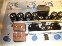
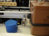
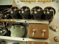
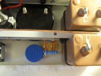
I had planned just 1 rail for the psu caps (Samwha gold for audio as recommended by Tim) I had discarded the second as it was a rough test piece. (note the scratches) but It worked so well that I decided to go with it anyway.
as I only had 2 of the 20mm stand-offs I had to make some brackets up with washers
as I only had 2 of the 20mm stand-offs I had to make some brackets up with washers
Attachments
Hi! Thanks for notes .That is intresting way for body this type amp audio-talk :: View topic - OTL by Tim Mellow
Did you plan sort tube In pare ?
Did you plan sort tube In pare ?
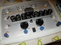
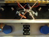
spent a few hours today on OTL project;-
1) Cap wiring done and all PSU wiring finished apart from main feed and switch.
2) All the grounds are to return to one point (star grounding) the 1.5sq mil copper may be overkill but it gave me good results on my Mullard 3-3 stereo amp
3) high precision 34k resistors (as specified by Tim) feed to the input caps, the centre earth pin on the tag strip is isolated from the metal rail using T03 transistor isolating kit parts, thus preserving the star grounding
4) I was short of a tag to connect the resistor between the bias pot and the input balance pot, after lots of head scratching came up with this.
progress is slow as I am spending more time working out the layout than soldering... but any Progress is Progress !!
Attachments
Looking good
I used High temp antex solder on my 6C33c sockets. (have you burnt the OP tubes in yet?)
I dont think the 1.5 is overkill. I use PTFE silver plated stranded 1.5mm.
And the speaker Gnd is 2.5mm from CT. (Its not a Tim Mellow)
Are your Hi prec resistors holco?
Regards
M. Gregg
I used High temp antex solder on my 6C33c sockets. (have you burnt the OP tubes in yet?)
I dont think the 1.5 is overkill. I use PTFE silver plated stranded 1.5mm.
And the speaker Gnd is 2.5mm from CT. (Its not a Tim Mellow)
Are your Hi prec resistors holco?
Regards
M. Gregg
Last edited:
- Home
- Amplifiers
- Tubes / Valves
- New Tim Mellows OTL project