I'd go with the largest values you can- at higher power levels, the extra bypass amounts to lower IM which is heard easily enough.
We use a total of 12,000 uf in the supplies of our 60-wat amps- that seems to be at the point on the curve of vastly diminishing returns.
I tried paralel caps for the same reason, but the result was not good. Shall be an isue icreasing inductance by puting them in paralel? In anny case listening tests with those ones was from far the best.
Attachments
I tried paralel caps for the same reason, but the result was not good. Shall be an isue icreasing inductance by puting them in paralel? In anny case listening tests with those ones was from far the best.
Were you comparing the sound of the paralleled capacitors with the sound when instead using larger single capacitors that achieved the same total capacitance as that of the paralleled composite capacitors? Or were you instead comparing the sound for the paralleled capacitors with the sound before adding the extra capacitors in parallel?
In other words, were you comparing like with like; that is to say, comparing the effect of having the same total capacitance, achieved either by using paralleled smaller capacitors versus single larger capacitors? Or were you instead comparing the sound for larger total smoothing capacitance versus smaller total smoothing capacitance? If it was the latter, then it was not really a test of the audible effects of using paralleled capacitance per se, but instead merely a test of the audibility of using different amounts of total capacitance.
Using different total amounts of smoothing capacitance will have the effect of changing the low-frequency roll-off; a little bit like the effect of a low frequency tone control. Maybe, if you were in fact comparing the sounds for different total values of smoothing capacitance, it just happened that the effect of having a bit more roll off sounded pleasanter in your specific set up, and to your auditory tastes.
Chris
Getting to the point, first of all I am listening the Tim's OTL on my Quad's ESL 63.
The PSU caps test was:
2x1800 Nipon-Chem per raill = sound good detailed but lack of bass
2x2500 Panasonic per raill = sound good detailed but lack of bass
4x1800 Nipon-Chem per raill = sound lacks of details, less soundstage lack of bass
2x2200 Kendail per rail = more detailes but same lack of bass
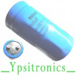
2x1500 Philips per raill = more details, more sound stage, much more bass & punch
The caps were paraleled with 14uF Arcotronics MKP
I think to repeat the test with Mundorf Mlithyc 1500uF/500V but the investment stps me for the moment.
Getting to the point, first of all I am listening the Tim's OTL on my Quad's ESL 63.
The PSU caps test was:
2x1800 Nipon-Chem per raill = sound good detailed but lack of bass
2x2500 Panasonic per raill = sound good detailed but lack of bass
4x1800 Nipon-Chem per raill = sound lacks of details, less soundstage lack of bass
2x2200 Kendail per rail = more detailes but same lack of bass
2x1500 Philips per raill = more details, more sound stage, much more bass & punch
The caps were paraleled with 14uF Arcotronics MKP
I think to repeat the test with Mundorf Mlithyc 1500uF/500V but the investment stps me for the moment.
I have never been able to relate to concepts such as detail, punch or soundstage; they are expressions I see people using, but I have no real idea what is meant, or how one would quantify them. Stronger or weaker bass, on the other hand, should be a quantifiable, with the aid of a signal generator and output voltage measurements. Curiously, you seem to be hearing the strongest bass in the case of the smallest values of smoothing capacitor (2 x 1500 uF), which suggests perhaps that the sound quality that comes across as seeming like "strong in bass" is really something else that creates an auditory impression of stronger bass.
I can imagine there are so many variables at play, including specific details of the frequency response of the speakers, possible LC resonant effects (speaker inductance vs power supply smoothing capacitance), and so on, that it may be hard to extract any robust universal lessons about optimal choices that would apply in the broader setting of other systems.
I can only express admiration for anyone who is able to carry in their mind such precise impressions of how a particular configuration sounds, so that they can make a meaningful comparison with a how a different configuration sounds after some delay while swapping the capacitors in the power supply! It is quite beyond my own personal experience. The only comparisons I personally would be able to make are those involving measurements.
Chris
Dear Cris,
Thanks for your interest in that project and sharing your point of view.
As I am not a professional but a dam good listener since 1954, listening live opera and simphonic orchestras "forced" by my parens jobs, I dare to put this isue in a philosophical way:
Are we interest in building those nice devices for listening or scientific research ?
Some people shall see finality one way or an ather.....I am for listening...but yes measurements I consider very important. I do my best but I repeat I am not a professional so I am learning evry day from ather people .
I have never been able to relate to concepts such as detail, punch or soundstage.
Chris
I find this terminology hard to understand too, although I will say that, during my time as a broadcast and recording engineer, the term "punch" was frequently used by producers in their quest for higher ratings. On my part it usually involved grossly interfering with the dynamic range and fiddling around with the upper bass frequencies. Of course this is not relevant to a discussion about smoothing capacitors.
I find this terminology hard to understand too, although I will say that, during my time as a broadcast and recording engineer, the term "punch" was frequently used by producers in their quest for higher ratings. On my part it usually involved grossly interfering with the dynamic range and fiddling around with the upper bass frequencies. Of course this is not relevant to a discussion about smoothing capacitors.
Sory for my english terminology, I apologise. Of corse, as you mentioned, is not relevant to that discussion. I am sory too leaving that thred without sharing wih whom is interested, my ideea's and projects.
Sory for my english terminology, I apologise. Of corse, as you mentioned, is not relevant to that discussion. I am sory too leaving that thred without sharing wih whom is interested, my ideea's and projects.
I was actually referring to my own use of the word. I'm sure all comments and opinions, however said, are welcome in the discussion; no need to be sorry about anything.
IMO, the smoothing capacitance should be divided or spread over 1 or 2 pi sections with tapper capacitance towards the load, not everything in one section, in doing the difference in characteristic of different brands can be minimized or customised for best result.
Last edited:
IMO, the smoothing capacitance should be divided or spread over 1 or 2 pi sections with tapper capacitance towards the load, not everything in one section, in doing the difference in characteristic of different brands can be minimized or customised for best result.
Can you post a diagram in order to explain better the ideea?
I was actually referring to my own use of the word. I'm sure all comments and opinions, however said, are welcome in the discussion; no need to be sorry about anything.
thanks
Can you post a diagram in order to explain better the ideea?
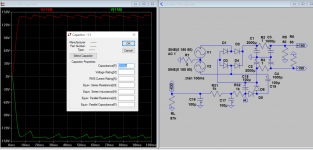
Right, something like this, add the ability to modify the series, parallel resistance, inductance, such as pi section.
Edit R5, R6 is test load 50 Ohms
Attachments
Last edited:
Right, something like this, add the ability to modify the series, parallel resistance, inductance, such as pi section.
Edit R5, R6 is test load 50 Ohms
And if R1 = 1k - 0,5K what happens ?
One of our customers placed a microphone at the listening position and used that for frequency response and distortion measurements after changing power supply caps. So he could quantify what what he heard with points on a chart. When you get to auditioning parts, this might be one of the better ways of doing it.I have never been able to relate to concepts such as detail, punch or soundstage; they are expressions I see people using, but I have no real idea what is meant, or how one would quantify them. Stronger or weaker bass, on the other hand, should be a quantifiable, with the aid of a signal generator and output voltage measurements. Curiously, you seem to be hearing the strongest bass in the case of the smallest values of smoothing capacitor (2 x 1500 uF), which suggests perhaps that the sound quality that comes across as seeming like "strong in bass" is really something else that creates an auditory impression of stronger bass.
I can imagine there are so many variables at play, including specific details of the frequency response of the speakers, possible LC resonant effects (speaker inductance vs power supply smoothing capacitance), and so on, that it may be hard to extract any robust universal lessons about optimal choices that would apply in the broader setting of other systems.
I can only express admiration for anyone who is able to carry in their mind such precise impressions of how a particular configuration sounds, so that they can make a meaningful comparison with a how a different configuration sounds after some delay while swapping the capacitors in the power supply! It is quite beyond my own personal experience. The only comparisons I personally would be able to make are those involving measurements.
Chris
And if R1 = 1k - 0,5K what happens ?
There will be very little output voltage, R1 should be < 1 ohm to avoid big drop. No offend intended, it's normal done like this, after-all you have built it, else can do another way like you said. I just try to explain. Apart from hearing using ears you can use a pc spectrum analyser and microphone, using tone rather than music, after you notice the difference, then audit it.
I am wondering how important it is to have R7 (470K, 2Watt) specified as 1% tolerance. I'm having trouble sourcing this resistor. I have access to 5% tolerance resistors at that value. All comments welcome.
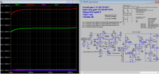
According to my sim it's about 1V variation in bias with 5% tolerance R7 470K:
-49.5V/199.6 (446.5K) to -50.9/-201 (493.5K)
It's not a big noise source, input resistor R1 is biggest. What do you think about total noise figure?
Attachments
Last edited:
According to my sim it's about 1V variation in bias with 5% tolerance R7 470K:
-49.5V/199.6 (446.5K) to -50.9/-201 (493.5K)
It's not a big noise source, input resistor R1 is biggest. What do you think about total noise figure?
In practice, noise is not an isue for Tim's otl design. On my opinion the sensitve part of the design is around the ecc83 LTP. Better it works, better the amp sounds.
I wonder what's the purpose of 1ohm R16,17 on the 6c33c cathodes?
In practice, noise is not an isue for Tim's otl design. On my opinion the sensitve part of the design is around the ecc83 LTP. Better it works, better the amp sounds.
I wonder what's the purpose of 1ohm R16,17 on the 6c33c cathodes?
In Tim's sch they don't exist, but are for current meter monitoring, also for tube fault short circuit current limit, value vary from 0.1 to 10 ohms depend on the tube, exist also in solid state output stage. Also some local feedback.
Since you touch on ecc83, have you use different brand? I can hear they all sound different. And also the driver, are you stuck with ef86 only? That is why others and I have suggested to use spectrum analyser to make check harmonics because it can give you many clues not just the sch also the tube itself. ECC99 has more odd harmonic than 6N6P, hence it sounds brighter in my amp. Please read this article for leisure. In my practical LTP sounds less congested the concertina. I also moved gNFB to 2nd grid of LTP, this has freed the input somewhat from very busy work. This the sim I already have, I can post it if anyone want to see.
What load impedance you have on the output? It's 32 ohms or higher? I have some findings on simulation on different loads, it may be a concern if you use higher load impedance, because totem pole has to be realigned to work on higher load, the current of top and bottom will not be fully symmetrical and maybe in Class A mode with one side conducts more than the other. So this is only simulation finding. It may concern me also as I intended to hook 32 ohms or more headphone directly to output, so I will hear really how it sounds as well as spectrum / scope monitoring. In the sim a small amout of NFB is feeded to top of 2nd LTP cathode, so the output current is synchronised and symmetrical.
Attachments
Last edited:
- Home
- Amplifiers
- Tubes / Valves
- New Tim Mellows OTL project