GROOVEWATT RIAA
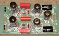
I decided to do a PCB based on the groove watt design. I've used SRPP stages before and they have been great sounding gain stages with low noise.
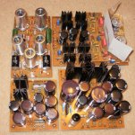
Input is tuned to the B&O specifications, 47k and 220p input termination for the MMC-20CL/MMC-20EN. It is based on 12AX7 / 12AD7 tubes and output buffer is a 12AT7. To keep the cost down, it is designed for toner transfer PCB in a sink, DIY style. I use a chunk of the floral foam to do a mock-up to verify component spacings prior to etching a PCB.
It was designed for use with shielded tube sockets to minimize noise/hum. Some of the resistors are parallel stacked to get to 1% of the required values for the comp poles. I've designed an elevated 12VDC regulated supply for the heaters due to the SRPP stage configuration. Space inside the amp was limited and resulted in the size and shape to fit in with the other PCB's. (6.6" x 3.6)
I decided to do a PCB based on the groove watt design. I've used SRPP stages before and they have been great sounding gain stages with low noise.
Input is tuned to the B&O specifications, 47k and 220p input termination for the MMC-20CL/MMC-20EN. It is based on 12AX7 / 12AD7 tubes and output buffer is a 12AT7. To keep the cost down, it is designed for toner transfer PCB in a sink, DIY style. I use a chunk of the floral foam to do a mock-up to verify component spacings prior to etching a PCB.
It was designed for use with shielded tube sockets to minimize noise/hum. Some of the resistors are parallel stacked to get to 1% of the required values for the comp poles. I've designed an elevated 12VDC regulated supply for the heaters due to the SRPP stage configuration. Space inside the amp was limited and resulted in the size and shape to fit in with the other PCB's. (6.6" x 3.6)
Attachments
This is my first attempt at a RIAA phono amp also. I wanted a passive design between two gain stages. I used a SRPP stage in a previous project and was happy with the way it turned out, very quiet and dynamic.
After researching I found that it is very similar to the Aikido tetra phono amp. There was controversy over the time constant for the cutter head~50khz and its 3.18us RC time constant. Some folks believe that it is responsible for correcting the hi frequency phasing more so than for correcting amplitude profile. I love a little controversy, so I want back and added room for a 680pf cap and 4.7k resistor.
SO what is really needed for a great phono preamp that we can all use as design rules?
Is the 3.18us really necessary?
no ground loops
shielded tube sockets, grounded
filtered B+, slow start
filtered DC on the heaters
low noise matched tubes, 12AD7, old bungle boy 12AX7, etc ( I'm on 12.6 volt supply)
accurate RC time constants, account for impedance driving and loading the RC stack
There must be a preferred cap like PIO, but I'm using wima and metalized poly...
Metal film or carbon comp resistors? I was going metal film..
Don't use chassis ground as signal ground
What else is a design and fabrication consideration?
If I was not limited on size, what components would be ideal?
Brommermartin, nice chassis! I'm not that good on wood work or sheet metal work. Everyone keeps raising the chin bar with their great designs! It is good inspiration on what is possible.
Last edited:
I don't know what your calculations are for the passive section, try a simple version example:
http://www.kabusa.com/riaa.htm
A quick play shows it jives with several proven RIAA designs.
SRPP stage would have lower output impedance less influenced by the RIAA section.
http://www.kabusa.com/riaa.htm
A quick play shows it jives with several proven RIAA designs.
SRPP stage would have lower output impedance less influenced by the RIAA section.
They aren't my calculations. But I'm glad to hear that they look good.
An SRPP stage where, I'm guessing you mean the cathode follower final stage?
Is there any real point in the various impedance selector resistors at the front end? Wouldn't just the 1K be enough?
I plan to eventually build this thing, but it may be a while. I'm in the middle of a main amp first.
An SRPP stage where, I'm guessing you mean the cathode follower final stage?
Is there any real point in the various impedance selector resistors at the front end? Wouldn't just the 1K be enough?
I plan to eventually build this thing, but it may be a while. I'm in the middle of a main amp first.
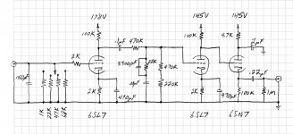
For my B&O, it states 47K and 220p required for the termination load on the cartridge. So you would couple this with a grid stop resister to the first stage 1k should be fine. I prefer a SSRP first stage with a low output impedance driving a conventional RC stack. Go to the Kubasa link above and plug in different values for the coupling resistor and watch the required RC values change. It will require a cap to isolate the first from the second stage. I chose a .47u wima, and have a .47u PIO on order. You should have a grid stop resistor on the second stage large enough that does not load the RC stage. The second stage is a gain stage to help compensate for the loss in the RC RIAA section and the output should be able to drive any input to a pre or power amp. I use 100K pots on the inputs so I wanted a lower output impedance with more drive that you have. I also found a 4.7u output cap to prevent from rolling tooo much of the the low end, I believe the .22u would act as a rumble filter. Looks like you would only have about 1.5 ma drive on your output stage....
Thanks. This is the kind of feedback I wanted. I see I misworded a question that must have caused you to miss one thing I was getting at. My question should have been - of the four selectable impedance resistors in the front with the switch, are these four different resistors really necessary or would just the 47K be enough? (I mistakenly said 1K.) I thought nearly everything required a 47K for proper impedance matching to the cartridge. It almost looks like a selectable capacitance would be more useful, rather than a selectable resistance, no?
I'm a little puzzled about the RIAA calculator you showed me. My R/C component layout doesn't look the same as that one, so I don't get the values to match up.
Isn't this what the .1uF cap is between the first and second stages?
And isn't the 470K directly after that .1uF the second grid stopper you mention, or is that part of the RIAA network and you're saying there should be another resistor directly in front of the second stage at the grid? What value would be good for that? Another 1K, like you mentioned in front of the first stage?
Good grief, that .22uF output cap is very low isn't it. I double checked and that's what was written on the diagram. I should have seen this one myself. That should be more like 2.2uF at least, if not the 4.7uF you suggested.
And again on that output impedance. Wow. Hey, I just rotely copied down the diagram and didn't pay a lot of attention to some things. Since I will also use 100K pots on the main amp input, a 10K would be more appropriate than the 1M, correct? And this 2.2uF/4.7uF and 10K would give better output drive?
I just reread the whole thread and I see where in the first circuit posted here, the guy went from a 22K output resistor up to a 220K. So a 10K would be too low? Admittedly I don't understand it all, and much of what I understood some years ago I have forgotten from not looking at some of this stuff for a long time.
I'm a little puzzled about the RIAA calculator you showed me. My R/C component layout doesn't look the same as that one, so I don't get the values to match up.
It will require a cap to isolate the first from the second stage.
Isn't this what the .1uF cap is between the first and second stages?
And isn't the 470K directly after that .1uF the second grid stopper you mention, or is that part of the RIAA network and you're saying there should be another resistor directly in front of the second stage at the grid? What value would be good for that? Another 1K, like you mentioned in front of the first stage?
Good grief, that .22uF output cap is very low isn't it. I double checked and that's what was written on the diagram. I should have seen this one myself. That should be more like 2.2uF at least, if not the 4.7uF you suggested.
And again on that output impedance. Wow. Hey, I just rotely copied down the diagram and didn't pay a lot of attention to some things. Since I will also use 100K pots on the main amp input, a 10K would be more appropriate than the 1M, correct? And this 2.2uF/4.7uF and 10K would give better output drive?
I just reread the whole thread and I see where in the first circuit posted here, the guy went from a 22K output resistor up to a 220K. So a 10K would be too low? Admittedly I don't understand it all, and much of what I understood some years ago I have forgotten from not looking at some of this stuff for a long time.
Last edited:
The .1u coupling cap between stages will have a 80k resistance at 20hz which adds to the 470k resistance value , about a 17% change. A .47u only has a 4% change at 20hz. The .1 will cut the rumble, but my personal IMHO, it is too much influence on the RIAA stage.
On the second stage I'm using a 22K grid resistor at the tube socket instead of a 1k. The increased value will reduce the miller capacitance's effect on the RIAA section.
Bias on the output tube is for operating in the sweet zone and for sufficient drive. I choose a value of IQ in the 10ma area and I believe the 6SN7 also would like to run in this area, so 20K cathode resistor to ground for my B+ chosen. The 4.7u output coupling cap has a resistance of 17K at 20hz which is very small compared to the ground reference resistor and input resistance to the amp or pre-amp of 100k. so if you use a 100k to ground and 100k on the next stage its 50k equivalent and the cap effect is only about a 3% loss at 20hz. So for my values I have about a 8% total circuit loss at 20hz for my rumble filter, for your selection about a 36% loss added to the interstage coupling loss mentioned above.....say about a 50% loss.
Verify my ramblings, but there could be meaning behind my madness.
I do not know of the RIAA comp circuit that you selected. You would have to run a spice sweep on it to confirm the response, or just use one that is proven from the web site calculator above...
I also add the 50k controversial comp for the cutter head as the 4th RC time constant in the RIAA portion. I' don't have to stuff it , but the provisions will be in the PCB if I want too.
I have the RIAA PCB and 2 power supply PCB's to toner etch and fab to try out my version. Keep us posted on your fab and testing. The beauty of this site is that there are so many ways to do the same thing. I love the creativity and diversity of design!
After some tweaking the phono amp is better sounding but not as I expected
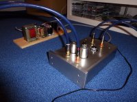
In the mean time I have built the Phonodude because I had the parts laying around and it is a well known design here in the Netherlands.
The result is a very nice phono amp with no hum or hiss.
In the mean time I have built the Phonodude because I had the parts laying around and it is a well known design here in the Netherlands.
The result is a very nice phono amp
with no hum or hiss.Attachments
TriodeDick and the Groovewatt are similar in topology. Congrats on getting it completed!!, I'm still etching power supply PCB's for the RIAA Amp and have a few components still to source. I'm looking forward to sitting in the man-cave with a cold one enjoying old vinyl....
Attachments
Seeing as this is a 6SL7/6SN7 phono preamp thread, I would like feedback and comments on this circuit. TIA.
I *really* like that cartridge load selector! All things considered I'd just pick values that work best for the cartridges I own, and keep 47k around "just because." I have this old cheap Grado cart that sounds pitiful until you load it down to about 10k. At that point it sings better than Joe Grado did, and that's saying something. Some high output moving coil carts may "like" another load besides 47k.
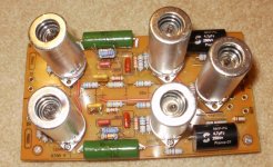
Finally had time to "fire-up" the modified "GROOVEWATT" RIAA preamp. I still need to add a couple of B+ bypass caps on the PCB, but found it quiet as a church mouse without them. The 220v B+ and the elevated 12VDC for the heaters in on two separate PCB's.
I have a B&O turntable so I used the recommended 220p and 47K terminating input impedance for the MMC cartridge. I measured all of the RIAA caps and resisters to ensure 1% matches to calculated and each channel.
The tubes could be changed to 12SN7 and 12SL7 for those that prefer octal flavor. This project is a thumbs up and recommended to others that want to brew their own.
Attachments
Last edited:
No plans to produce, just sharing what can be done in a sink with the toner transfer method of home PCB fabrication. I have it up and running but need to place in a chassis. I've put this on hold to work on a couple amps, one will sit on top of the preamp and the chassis will be made from a slab of Brazilian cherry. I wanted the grain to match and wrap around the amps. The other amp is a 6LU8 PP designed PCB, Fixed or cathode biased, triode, pentode or UL on the output. With or without slow B+ damper diode warm up feature. Should be in the 25 watt /channel region. I'm trying to get projects lined up for the long cold winter nights. I found a set of 30 watt Bogen outputs 6.6k and a ST70 power transformer to play with.
Last edited:
I've fired up the PCB's many times , tweaked a few values in the Hybrid Tube-MosFet Amp and dusted off some 35+yr old vinyl. I purchased an assortment of short plate and long plate tubes with Gm from 20 to 100 to roll. So far I like smooth plate 7025 on the first stage, Raytheon 6414 on second stage and 7062SQ as the follower. Most of my vinyl has been untouched for 35yrs, it is like a new toy. The extra windings I put on the toroid works with the exception of running all long plate tubes and swapping 6AK10 tubes for the 6AC10 tubes. Tooo much heater current and the toroid gets hot. I've got a request into Edcor for a custom transformer for this application.
- Status
- This old topic is closed. If you want to reopen this topic, contact a moderator using the "Report Post" button.
- Home
- Amplifiers
- Tubes / Valves
- 6SL7 / 6SN7 Phono