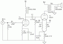
Hi All, I have a GM70 project on the bench and it has been sitting for quite a while now. Here is the issue: I know how to build thinks but I really do not understand how an amp actually works and if I am going in the right direction. I have the PS all worked out and have the components so I will get 850v B+ DC, but I want to use Nicholas Chua's schematic (attached) but he built his amp using 400v B+ and plans on going up to 750v B+ at some point in time.
SO.....do I just up the voltage on the parts I use, or do I have to rejigger the other values for some reason?
Also, where can I find chokes valued at 100H, 850R?
SO.....do I just up the voltage on the parts I use, or do I have to rejigger the other values for some reason?
Also, where can I find chokes valued at 100H, 850R?
Attachments
Don´t want to be negativ but if you can´t read and understand a tube diagram, don´t change anything in the design.
Post the circuit disgram for your PSU and perhaps we can tweak it to deliver the 400v you need.
The choke you´re looking for is called plate chokes and are made to work with one type of tube so not generic like a PSU choke.
Post the circuit disgram for your PSU and perhaps we can tweak it to deliver the 400v you need.
The choke you´re looking for is called plate chokes and are made to work with one type of tube so not generic like a PSU choke.
I can read the schematic and build whatever I see, I just don't know enough to understand what values, besides the higher voltage, needs to be changed, if any, to push the B+ higher. I also worked on ship board radar for 4 years in the Navy and I am skeptically comfortable with high voltage.
I did not take your comment as negative, only cautious....that is a good thing: thank you.
I did not take your comment as negative, only cautious....that is a good thing: thank you.
It´s not just that you have to change some components.
You may have to change the output transformer.
A tube is sounding differently at different voltage/current and this is a matter of taste.
So for a start build a working concept read some of the the good online tube how to´s around.
Then you can based on your new won knowledge start tweaking your working amp to find out IRL what changing working condition of the tubes does to the sound.
Building a tube amp from scratch without the basics will probably end with a meltdown and an unfinsihed amp in the closet.
This comes from a guy that has rebuillt his latest amp dozens of thimes blowing up parts and in the end didn´t manage to get it to fit the box but it´s learning.
You may have to change the output transformer.
A tube is sounding differently at different voltage/current and this is a matter of taste.
So for a start build a working concept read some of the the good online tube how to´s around.
Then you can based on your new won knowledge start tweaking your working amp to find out IRL what changing working condition of the tubes does to the sound.
Building a tube amp from scratch without the basics will probably end with a meltdown and an unfinsihed amp in the closet.
This comes from a guy that has rebuillt his latest amp dozens of thimes blowing up parts and in the end didn´t manage to get it to fit the box
but it´s learning.I know the transformers are rated for the called out spec in the schematic and are rated for the B+ I am using, so that should not be an issue. I'll do reading and talking. I can relate to starting in one place and ending up without the needed room. A couple years ago I built a hydraulically driven motorcycle and the hydraulic pump and motor are too small so now I have to chop the frame in half and lengthen it 6 inches.....
I was talking about the output transformer not the powertransformer.
If doubling the B+ the primary winding of the outputtransformer has to be changed for correct loading of the tube.
You can raise the B+ but when you excide the max dissipation for the tube V*A the tube will fry.
So raising the voltage you have to back of on the current.
If doubling the B+ the primary winding of the outputtransformer has to be changed for correct loading of the tube.
You can raise the B+ but when you excide the max dissipation for the tube V*A the tube will fry.
So raising the voltage you have to back of on the current.
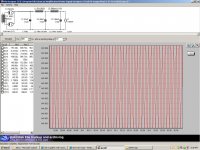
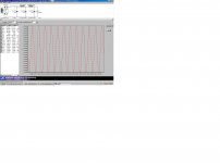
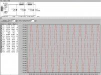
OK, I understand. The PS for this was not taken from Nicholas Chua's schematic. Me and Kegger designed it. My PTX is 750-0-750 and with all the chokes and caps, it is showing 850v with very very little ripple. The chokes in the PS offer very little resistance as well. Here is the screen shot of what we have in hand and the components the top plate was cut for. The top plate is 3/8 aluminum.
Interesting... I just noticed that I have 650v in that shot not 750. I'll have to go back and change that.
Interesting... I just noticed that I have 650v in that shot not 750. I'll have to go back and change that.
Attachments
Yes, Heybour wound the OPTs specifically for this project. I am using big oil cans. Right, I have 1300v ct so that should get down to 850v after cap loading.
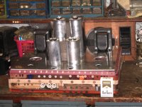
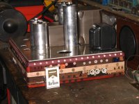
Here is a couple pix so far. I posted these a year ago, but I had to put the project away while I looked for work and a new place to live. All the parts are painted (not shown) and the oil caps are polished. I just need to finish up the woodwork and I can start wiring.
Here is a couple pix so far. I posted these a year ago, but I had to put the project away while I looked for work and a new place to live. All the parts are painted (not shown) and the oil caps are polished. I just need to finish up the woodwork and I can start wiring.
Attachments
Last edited:
What specs for the opt´s
I will have to go back and find the specs. It was 4 years ago they were wound.
- Status
- This old topic is closed. If you want to reopen this topic, contact a moderator using the "Report Post" button.
- Home
- Amplifiers
- Tubes / Valves
- I need help with my amp project