Good morning Chris...
Your circuit may work, but you should consider increasing the value of the 50 meg resistors. If you consider the equivalent grid circuit with respect to the high impedance of the capsule (typically 40-50 pF) and audio frequencies, you have the 50 meg grid resistor in parallel with 100 meg polarizing circuit which results in an equivalent 33 M impedance (with respect to audio) across the capsule. The 2 meg resistor and 0.1 uf capacitor decouples the polarizing supply so this is not considered. The leakage resistance of a 7586 tube (approx. 1000 megohms) is negligible. You should increase the grid and charging resistors to make the equivalent audio circuit resistance (with respect to the capsule) on the order of 150 megohms.
Last but not least, the 30 k and 100 k series divider for the capsule polarizing voltage puts 88 volts across the capsule as shown. The "target" voltage for the mic capsule should be 60 volts, so change the 30 k resistor to 100 k and this will put 58 volts on the capsule, close enough. The 100 k plate resistor and 5 k cathode resistor should work; the 7586 plate current should be on the order of 0.5 milliampere and the plate voltage (across the tube) should be around 60 volts with those values. The 5 k cathode resistor effectively sets the operating point of the tube so be careful when changing that value. A lower resistance will lower the grid bias and the tube will draw more current and vice versa. The resistors and capacitors should be good quality since any noise generated by noisy resistors or capacitor leakage will be amplified in the circuit as shown.
Measure voltages with a vtvm/fet vm to avoid loading high impedance circuits. A 20,000 ohm per volt meter loads high impedance circuits.
Chris: One other item worth testing: The cable between the power supply and the microphone. If you have a AKG C60 or one of those minature tube mics (i.e. KM54, M221A,B, etc), check the cable carefully, especially at the mic end. The conductors are very thin and I found a break in my M221 cable on two of the conductors. The cable can be tested for continuity and shorted conductors using an ohmmeter. The conductors are probably 22 gauge stranded, and have thin insulation. Probably going to have to call Neumann and see if they still sell bulk multiconductor cable for the KM54...old cable with the extremely thin insulation with 120 volts of HT on it may be deteriorating...I cut back the mic end and reinstalled the Tuchel connector and the mic came back to life but that old cable....
The point I am making is that you can spend a lot of time working on a mic but if the interconnect cable is bad, anything you do with the mic is wasted time. The guy I got the mic from several years ago told me the AC701k was bad and didn't want to spend the money to replace it. Turned out the AC701 was perfect....
Good luck...
Chris, are you modifying a real C60, or is this a new build of a C60? I recall reading that you built a C60 using a 5703 subminature triode. I just finished working on a M221A Telefunken/Scheops mic. This mic is similar to Neumann's KM54 and both use the AC701k.
The AC701k is run very conservatively and should not go bad...even though a mic I have had for over 30 years had two bad AC701's in it when I got it. My mic was from a studio where it probably was left on whether or not it was being used, and the AC701's were noisy when I tested them on a test fixture. Power supply problems or noisy resistors/leaking coupling cap can create noise. The last thing you want to do is "condemn" a AC701, since you are either into a very expensive replacement or a modification to keep the mic running. I modified the circuitry in my mic for 7586's but the capsule bias was NOT derived from the cathode in my mic..
Since the capsule bias IS derived off the tube cathode in the C60, you have to add/change some resistors to use the 7586 nuvistor. Use 0.5 watt metal film resistors to minimize noise. You need to install a nuvistor socket in the mic and face it so the grid pin can be directly wired to the capsule with a short piece of solid wire. Ground the shell of the nuvistor using a piece of #20 solid copper closewound 3 or 4 turns around the nuvistor shell, the other end connected to a stable ground point. Use good quality (teflon) #22 wire to connect the heater, plate and cathode circuits of the nuvistor into the mic circuitry. Route this wire bundle away from the grid. Here are the rest of the mic modifications.
1. Add a 4.7 k resistor in series with the nuvistor plate and HT.
2. Make a series divider with a 560 ohm and a 27 k ohm resistor. Open end of 560 ohm resistor to 7586 cathode. Open end of 27 k ohm resistor to ground.
3. Connect 180 meg ohm resistor to capsule to junction of 27 k and 560 ohm resistors.
4. Connect output coupling cap to the 7586 cathode, watch polarity, plus side to cathode. (Make sure voltage rating of this cap is at least 75 volts; preferably 150 volts)
In the power supply, you will need to remove the 4 volt zener diode and replace it with a 6 volt zener diode....you will have to reset the heater voltage to 5.6 volts with the supply loaded with a 45 ohm resistor (5 watts) across the heater pins, or with the mic connected. If you use a resistor for the initial setting, the final adjustment should be with the mic connected. You must have the zener diode in place to crowbar the supply in case something happens and the heater voltage increases beyond safe limits. The 7586 isn't necessarily pocket change so the heater voltage must be protected. With the mic connected and heater voltage stabilized, check the voltage at the junction of the 560 ohm and 27k ohm resistors with a vtvm. The voltage should be around 60 volts. If this voltage is excessive, you can collapse a mic capsule. If the voltages are OK, shut off power and reassemble the mic. Connect the mic to a good headphone amplifier and listen for artifacts while increasing the gain. Hopefully, you will hear background sounds with a low electrical noise floor.
Be careful when working on this mic or the power supply; the voltages in the equipment are hazardous and the HT filter capacitors will hold a charge for a while when the power supply is turned off.
Chris: 0.25 watt resistors will work fine. If you build the self bias circuit with the 4.7k in series with HT, you may need a 9.1 k in parallel with 10 k on that one. Try a 4.7 k first (tack it in temporarily) and measure the voltage drop across it with a vtvm. If you are seeing more than 25 volt drop across the 4.7 k resistor, you need the parallel combination. (I am leaving some power headroom since these components are working inside a closed space.)
Be careful because the 4.7 k resistor is at HT potential off the supply.
Be careful because the 4.7 k resistor is at HT potential off the supply.
Chris: Do you have a U 47 with the VF14 in it? Or is this a new build? If you have a U47, the conversion is built as a plug in, so you have to make a template of the VF14 pins, transfer that to a suitable piece of 1/8 or 3/16 in thick plexiglass, and use 0.7 mm brass screws to simulate the VF14 pins. Countersink screw heads into the plexiglass base to avoid shorts. Micrometer measure the pin diameter to be sure 0.7 mm is a good number for the plug in build.
New build can be done on plexiglass base and use a 9 pin ceramic socket that can take the small metal shield. The socket must be mounted with the pins toward the capsule, so the capsule connection can go to the grid pins via a short piece of solid wire. (The VF14 is a metal shell tube so the 407A should be shielded also.) The heater of the 407A is connected in series for 40 volt operation. (36 volts from the supply will work.) Countersink screw heads on the plexiglass base to avoid shorts. I will pull my notes and look up the rest of the values and connections.
New build can be done on plexiglass base and use a 9 pin ceramic socket that can take the small metal shield. The socket must be mounted with the pins toward the capsule, so the capsule connection can go to the grid pins via a short piece of solid wire. (The VF14 is a metal shell tube so the 407A should be shielded also.) The heater of the 407A is connected in series for 40 volt operation. (36 volts from the supply will work.) Countersink screw heads on the plexiglass base to avoid shorts. I will pull my notes and look up the rest of the values and connections.
Thanks for the tips, Now here comes the problem, the circuit for the c-60 becomes somewhat complicated, enough so that i need to use a breadboard, but i am concerned about the noise a board will inject, are my concerns valid?
And in this case, the VF 14 replacement is also a new build. Is it an exact replacement drop in, in this case?
Problem is too, I cannot find a good supply of the high value resistors, or the high quality capacitors.
Also, The capsule in the u47 has 3 legs, one is the backplate, one is the output, and one is shield/ground.
Can i connect the backplate to ground and polarize the grid side, and use a coupling capacitor to grid to rid it of the dc voltage?
Last edited:
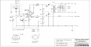
Chris: I need to look at my notes on the U47 mod. The 407A heater is 40 volts (sections in series using pins 1 and 9) with 50 ma heater current, but the heater is being operated at 36 volts for noise purposes...need to check other values and comments from my notes...The NG supply was a "brute force" supply with the heater and HT drawn off the 105 volt dc. If you are using 130 volts d.c. HT, you will need a 1880 ohm 10 watt (wirewound) resistor for the heater. You will burn open the heater using a 1K resistor!
This mod is not a direct "drop in"...there are some components involved. More later.
This mod is not a direct "drop in"...there are some components involved. More later.
Ok will make sure i use that bigger resistor then, I am not sure ive got one in that value however, so i'll see what i can do. Also it should be noted that I have the input in the microphone for a heater already, i could easily up it to 20 volts.
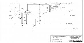
I am not understanding the 34 volts on the plate however, please check out the redrawn schematic for feeding the capsule polarization voltage.
I am not understanding the 34 volts on the plate however, please check out the redrawn schematic for feeding the capsule polarization voltage.
n60
in reference to the n60 .. i have a n60ea and pin 3 is not chasis ground but is a floating ground . in no way is it tied back to the chasis ... doing so caused a 60 hz hum also took out dc heater supply and replaced with a lm317 reg transistor that i built on a separate perf board. it is capable of up to 1amp of current . 5703 wants app.200ma of current to operate and will run a little hotter than a ac701"105 ma" . i have a c60 mic that i am replacing the ac701 with the 5703 tube ... not sure as of yet what the cathode resistor might need to be for 5703 tube anyone have any ideas. thanks
in reference to the n60 .. i have a n60ea and pin 3 is not chasis ground but is a floating ground . in no way is it tied back to the chasis ... doing so caused a 60 hz hum also took out dc heater supply and replaced with a lm317 reg transistor that i built on a separate perf board. it is capable of up to 1amp of current . 5703 wants app.200ma of current to operate and will run a little hotter than a ac701"105 ma" . i have a c60 mic that i am replacing the ac701 with the 5703 tube ... not sure as of yet what the cathode resistor might need to be for 5703 tube anyone have any ideas. thanks
hey after checking with my mic cable attached it is connected to chasis ..i was like you i still had hum .both ends of the cable have to wired exactly the same'' my shield was broken right before where it entered the connector... did you replace the 8 mfd. 150 volt cap connected to low side of transformer.this cap checked good on checker but was bad . this caused me problems with lots of low end from the mic ..there is 5 wires in the mic power supply cable plus the sheild connect pin to pin and with pin 3 and 5 split the shield wire and connect this shield wire to pins 3-5 along with other wires... when i did this hum went away ..has to be something to do with this being an unbalanced line from the mic to the transformer in the ps.....i did have to replace my voltage regulator with a lm 317 .i'm real pleased with the 5703 tube ..i have neumann km54's and this little mic blowns them away . it's hard to beleive that a mic with this size capsule can make things sound bigger than they are.. hope this helps if i can help let me know
Good evening Chris..
Most of the 1 % metal film resistors are quiet by nature and individual testing may be a waste of time unless you encounter one that is undeniably bad. Again, you can use a test fixture connected to an amplifier and connect a resistor in circuit (i.e. FET gate or tube grid leak) and listen for noise between several identical value resistors.
The AU7A capsule in my modified mike needs reskinned. Diaphragm is kaput. Don't want to "break the bank" getting the capsule reskinned either. Also looking for some thin nickel or sputtered mylar....
I find with interest about the "purists" saying the U47 must have the VF14 to be useable....I would love to get hold of a dead U47 and experiment with various tubes....the 407A mod was done to keep a friend of mine's mic as close to genuine as possible where the mod could plug in like the AR47 kit....but if someone wants that "sound" of the metal VF14, I wonder how a 12SJ7 (triode connected) or another metal tube (6F5, 6J5, etc.) built into a U47 would compare in A/B tests against a VF14 U47....sooner or later, the VF14's and AC701's are going to be history and some preparation should begin now.....
- Status
- This old topic is closed. If you want to reopen this topic, contact a moderator using the "Report Post" button.
- Home
- Amplifiers
- Tubes / Valves
- Tube condenser microphone help!