Btown, I prefer the 7586 nuvistor for use in a microphone. The 7586 has the same heater voltage as the 5703 but the input impedance is much higher and the self noise is much lower. I used the 7586 to replace the hard to find (and very expensive) AC701. You want to run the heater voltage on the 7586 at 5.6 volts since this lowers the "shot noise". All the resistors should be metal film, and the impedance coupling capacitor should be high quality mylar. The 180 meg ohm grid resistor is fine. I recall the plate resistor is 100 k (assuming a 150 volt dc supply.) I will attempt to post a schematic. The 6111 subminature may also work, but I haven't tried one of those.
If you are fortunate to own a Neumann U 47, my tube of choice to keep that running (if the VF14 is actually bad or the heater is open) is the 407A. The VF14 is extremely rare and expensive, and my understanding is that Neumann and Gotham Audio had the pick of the last run of the Telefunken plant on those.
If you are fortunate to own a Neumann U 47, my tube of choice to keep that running (if the VF14 is actually bad or the heater is open) is the 407A. The VF14 is extremely rare and expensive, and my understanding is that Neumann and Gotham Audio had the pick of the last run of the Telefunken plant on those.
btown2009: Getting line level off a typical condenser mic capsule will require two or maybe three gain stages. Inside the body of a small mic (i.e. AKG C-60 or Telefunken M221 style), this may be difficult to do even with nuvistors, allow room for the components, and keep undesireable interstage coupling down. The C-60 has a rather high output (compared to a dynamic mic) so you don't need a lot of outside gain. I normally pad a C-60 26 db before the preamp. You may be able to build a line level output in a larger tube mic where there is more room for tubes and the components. A tubed line level output stage will dissipate more heat than a simple follower circuit for a mic capsule since more undistorted voltage swing is required at +4 dbm than at -50 dbm. Check out the schematic for the Ampex 60 db plug in preamp used in the 351 and later recorders and mixers of theirs. The circuit is not suitable to interface a condenser mic capsule directly but uses two nuvistors for gain.
The nuvistor is a good low level tube. The 7586 in particular has a rugged internal structure to minimize microphonics and a special cathode structure for industrial service. A 6DS4 is useable but does not have the enhanced characteristics of the 7586. Neumann used the 7586 in the U-64 mic while its counterpart KM54 used the AC701. Run the regulated DC heater voltage on the 7586 around 5.6 volts to keep shot noise down.
The nuvistor is a good low level tube. The 7586 in particular has a rugged internal structure to minimize microphonics and a special cathode structure for industrial service. A 6DS4 is useable but does not have the enhanced characteristics of the 7586. Neumann used the 7586 in the U-64 mic while its counterpart KM54 used the AC701. Run the regulated DC heater voltage on the 7586 around 5.6 volts to keep shot noise down.
If you have space inside the mic for a 7586 nuvistor mounted so the pins face the capsule, and the 12A*7 type can be optimally placed, this may work. The metal can of the 7586 should be well grounded through a wire clip or other arrangement. For curiosity, what type of mic are you building this preamp for?
I have moved onto building my own microphones and have been doing alot of experiments and needed a good "push" in the right direction. I haven't experimented alot with nuvistors, so it is a newer field for me.
I thought about something like a 12ax7, but I have seen alot of 12bh7's in audio circuits for mic pres, and am still scratching my head at was best to use.
I thought about something like a 12ax7, but I have seen alot of 12bh7's in audio circuits for mic pres, and am still scratching my head at was best to use.
OK on your building your own mics...You may be better off using a 12AT7 or a 12AX7/7025 following the nuvistor input stage. The 12BH7 is a good audio tube but it may be noisy at low level. Are you taking the capsule polarizing voltage off the cathode of the nuvistor input tube as done with the C-60, or is the capsule DC from an external source? If you direct couple the plate of the nuvistor into the grid of the 12A*7 series tube, the plate resistor for the nuvistor must be carefully determined to apply proper B plus to the nuvistor, the sum of the plate and cathode resistors must be sufficiently high to prevent excessive plate current. The cathode and plate resistors for the next stage must bias the stage following the nuvistor correctly. With direct coupling, the plate voltage of the first stage is also the grid voltage of the following stage, and the B supply voltage must be somewhat higher to compensate.
It shouldn't hurt to run the regulated DC heater voltage low (5.6 v) on all the mic preamp tubes. Is the output transformer in the mic or are you sending unbalanced audio output to a transformer in the power supply as done with the AKG C-60?
I built a 7586 preamp into a dead Syncron Au7A but the capsule needs to be replaced...any leads on decent dual membrane capsules?
I've considered powering the capsule with an external source, however that would require more wires than what i have to work with in the cable.
Actually the 12at7 sounds like it may do the job very nicely, i've never thought about that, but i think 7025 would be even less noisy and could do the job better perhaps?
The capsules i am using are from thiersch i think is the brand, also neumann's are easy to find aswell and you should be able to find a decent replacement from them. Thiersch elektroakustik
If i perhaps asked you to help me do some calculations (and i must admit here i am not the best) could you help me?
I do highly appreciate your help with this project as you have helped me move further on this project than what i could have possibly done on my own.
Also what is wrong with the capsule you have? I have a friend who may be able to repair it, this guy is really good.
-Chris
Good morning Chris:
First, you want to use metal film resistors in any preamp. You may have to special order the high value 0.1 watt resistors used in the high impedance capsule circuits (i.e. 100 megohm, 150 megohm, 250 megohm, etc.) Under no circumstances use regular carbon resistors in a mic preamp. Remember carbon mics and the background noise?
Metal film resistors have a code that gives the value and type. For example, a 215 ohm metal film resistor has a part number RN2150F where the 215 is the first three significant digits of the resistance, the 0 is the added multiplier (in this case 10**0 or 1), the F is film, etc. The power rating may follow the F.
You can always construct a test fixture in a small metal minibox to simulate the preamp. I have two of them, one for miniature 9 pin and the other for nuvistors. My test fixtures have the tube plate (output) impedance coupled through a UTC A26 transformer (plate to line) to a XLR connector to connect to an external amplifier. The regulated heater and B plus are brought in from batteries or an external well filtered supply. Terminals are arranged in the minibox to facilitate changing components in the plate, grid, and cathode circuits. Component noise can be determined either by measurement, or by listening through a monitor amplifier. The condenser mic capsule (on the order of 35-45 pF) can be simulated using a fixed mica "postage stamp" or a variable ceramic trimmer capacitor set to the desired value.
For the 7586 nuvistor in a condenser mic, you will probably find the following values will work fine with a well filtered 120 vdc plate supply with 5.6 volts dc on the heater (or batteries):
a. Plate resistor: 110 k metal film 0.1 w (100 k works fine)
b. Output coupling capacitor (plate to primary of output trans.) 3.2 uF 150 v
c. Capsule loading resistor 150 meg ohms 0,1 watt (grid to ground; cold side of mic capsule straight to grid)
d. Cathode resistor 2700 ohms 0.1 watt (cathode to ground)
e. Plate supply bypass capacitor 0.0068 uF 150 v (supply side of 110 k plate resistor to ground)
f. Charge the capsule or load through a resistor divider (typically 600 k in series with 300 k, open side of 600 k resistor to 120 v supply, open side of 300 k resistor to ground); connect another series divider (5 megohms in series with 25 k ohms); 5 meg ohm side to the junction of the 600 k and 300 k resistors, bypass the junction of this divider (5 meg in series with 25 k) to ground with a 0.01 uF 150 volt capacitor, the open side of the 25 k resistor to the high side of the capsule or simulated load.
Typical American resistor values of 620 k in series with 330 k for one divider, 4.7 meg ohms in series with 24 k for the other should put approximately 40-45 volts on the "hot" side of the capsule or load and work fine. Plate voltage on the 7586 should run around 40 volts (38 measured) and plate current around 0.7 milliamp.
If you like the idea of batteries, 13 regular 9 volt batteries in series will give you the plate supply, and 4 "D" cells in series will give you the heater voltage. If you use batteries, connect them through a on/off switch. Bypass the heater with 470 uF 10 volts in parallel with 0.001 uF 400 v and the plate supply with 20 uF 150 volts in parallel with 0.001 uF 400 v.; connect each to the respective locations on the COLD side of the on/off switch. The parallel combinations of the supply bypass capacitors is intended to bypass any hum components (high value) and RF (0.001 uF) to ground. Electrolytic capacitors don't bypass RF frequencies well by themselves. The 0.001 uF capacitors should be good quality ceramic or mylar.
You can get "fancy" with the preamp simulator and the power supply. The power supply can be current regulated to bring the heater up slowly to the desired value. Feedback can be carefully applied in the preamp to balance the response or compensate for capsule "peaking"...
Sorry for the long post...I located and read over my annotated schematics from 1987 when I replaced the AC701k with a 7586 nuvistor in a mic...I need to redraw the 1987 schematic to include everything (including some feedback components) but this should give you some ideas to test components before installing them in a mic...
Last but not least...Use high quality contact cleaner (unlubricated) around to remove solder rosin, etc. from connections, especially in the high impedance grid circuit. Do not use the contact cleaner near a mic capsule.
Chris: If you built a AKG C 60 mic according to the schematic shown in the first part of this thread, the mic end is about as simple as it gets, and it too can be simulated. Filtered B plus (+120 volts) goes straight to the plate of the nuvistor. The two series resistors in the cathode are required and these are chosen to self charge the mic capsule from the IR drop across the 82 k resistor. The 1.5 k resistor is the cathode resistor and the output (to a transformer) is impedance coupled off the cathode. My calculations indicate the plate current of the AC701k (as shown) is around 0.8 milliampere. This would make the capsule charging voltage around 65 volts.
If you use the 7586 nuvistor to replace the AC701k, change the 82 k resistor in the cathode divider to 110 k and the 1.5 k resistor to 2.7 k. (100 k should work in place of 110 k) Resistors 0.1 watt each. The 180 meg ohm capsule resistor is fine. The charging voltage will rise to around 75 volts but this should work. If the capsule charging voltage is excessive (measured at the junction of the 110 k and 2.7 k resistors), the plate supply voltage must be reduced approximately 15 volts by increasing R6 by 10 k. R6 is selected so you want to send approximately 100 volts to the nuvistor plate with plate current of approximately 0.7 milliampere.
What you are looking for is a plate current of 0.7 milliamp, a drop across the tube of 40 volts dc, and the capsule charging voltage in the range of 60-70 volts dc, developed across the 110 k resistor to ground. Use a good quality high impedance dc voltmeter for the voltage measurements in the mic since you don't want the voltmeter loading these circuits.
The earlier simulation today was for a AC701k in a Neumann mic (like a KM54).
Hello,
Firstly i want to say i appreciate this huge amount of knowledge that you have shared with me.
Secondly, I am considering and thinking, what are the possibilities of using 2 or 3 nuvistors without the use of tubes? I believe that nuvistors do not have the power output that tubes have, but however, a chain of 3 in series should be able to drive the output of the microphone to line level.
I have enough room to stash even up to 5 nuvistors, and since they sound cleaner and better than most tubes, or at least from what i have heard, they have lower noise, this may be the best option. How would my circuit change if i wanted to use nuvistors instead of tubes to drive line output. Tonight i will research and attempt to sketch some circuits that may do this. When i have finished them i will have you look over them, if you will to check them and give me your opinion on how they would perform.
Thank you very much,
Sincerely and best regards,
-Chris
Good evening Chris...
The old Ampex plug in mic preamp for the MR70 tape machine used two nuvistors to get 60 db gain. Schematics of that preamp can be found on line. I used a MR70 once years ago...a great machine...also used the ATR100 which was also a great machine and those in between...until Ampex ditched the audio business.
Whatever you do with the mic preamp, the input stage is the key. That is the stage that matches and/or amplifies the small voltage variations from the high impedance input to a useable output with minimal noise. I am convinced that the 7586 nuvistor is your input stage. The AKG C 60 mic has good clean high output. You can use another 7586 following the input stage for more voltage amplification, but probably would not work as a line driver. The 7586 has a absolute maximum power dissipation of 1 watt.
Inside the mic body, you will have at least one tube (heater power 0.7 watt, other dissipation 0.1 watt). More tubes means more power (and higher range of signal levels) in a confined area so you don't want to cram so much in the mic body and heat stress the capacitors, risk of oscillation etc. You may get away with 5 watts total dissipation with a U47 type body, but a smaller mic body will run hot. A line driver could be as simple as a 6C4 or a 12AU7 impedance coupled to a plate/line transformer, even a 6DJ8 type, depending on the primary impedance of the transformer and the operating point of the tube section (or sections if paralleled). I like transformer output since that stops RF most of the time if you are recording near any radio or TV station antenna structures. There is also an interesting tube D3A which is European, which seems to be high mu (in triode connection) and can also handle some power. Haven't used the D3A myself but may be worth getting a couple to try on the test fixture...
Hello,
I am going to attempt to experiment with a 7586 and a 7895 nuvistor, and possibly replace the 7895 with a 12ax7 tube, or a 13cw4 nuvistor.
Would all of these be suitable for interchanging and experimentation?
The ampex mr70 used the 7895 and i found some other mics used the 13cw4.
Thank you, I am also attempting to build a sketch and will share this with you, but i guarantee i have some values and placement wrong.
Bear with me please, I am still learning about sketching circuits.
Chris: The 13CW4 nuvistor was part of a kit Gotham Audio sold almost 40 years ago to replace the VF14 tube in the U 47 and U 48 mics. The VF14 has not been manufactured for many years, and the AR47 kit was a 13CW4 replacement for the VF14. Do not use the 13CW4. The 13CW4 has a 13 volt heater and was used in the old series string TV sets. The VF14 had a 40 volt heater but in mic use it was run around 35 volts in series with a dropping resistor off the single B plus coming out of the NG supply.
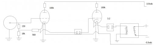
The 6CW4 nuvistor has a standard 6.3 volt heater. The 7895 is a high mu nuvistor triode with industrial specs. You should be able to use the 7586 off the mic capsule and follow that with a 12AX7. You may also want to experiment with running more plate current on the 7586 at the possible risk of more tube noise. If you are using the AKG C 60 circuit, try the following on the 7586 cathode divider: 18 k in series with 560 ohms, open end of 18 k resistor to ground, open end of 560 ohm resistor to 7586 cathode, 150 meg grid/cold end of capsule resistor to junction of 560 ohms and 18 k on the divider. The plate voltage (drop) across the tube should be around 65 volts, the drop across the 18k resistor should be around 54 volts, plate current 3 milliamps. The capsule voltage should be in the vicinity of 54 volts, the cathode voltage of the 7586 should be around 56 volts. B plus supply should be 120 volts. I recommend using the test fixture so you can use a high impedance voltmeter to check the voltages and a milliammeter to check current as well as facilitate easy component changes.
BE CAREFUL WHEN WORKING ON THESE CIRCUITS...The 120 volt B plus, filtered by many uF of capacitors, can do damage and/or seriously hurt someone. Be especially careful when measuring plate current since the milliammeter (or VOM meter) is at full supply potential! Allow capacitors to discharge before changing components.
Chris: The 13CW4 is noisy. It was mass produced and used as a RF amplifier in the UHF tuner of series string heater TV sets. The 6CW4 is the same tube electrically with a standard 6.3 volt heater. The 7895 is the choice for a high mu nuvistor since it has industrial ratings. The one U47 I heard with the AR47 kit (using the 13CW4) didn't sound as good as one with the original VF14 or a 407A mod.
I have started cleaning up a circuit which might help me, Sure im recycling it, but i think it might be a good start for me who doesn't have much knowledge of how to create good working circuits, I know the values are all different than what you were saying, but i found this one interesting as it had provisions for line output, and polarized the capsule via the ht supply.
Attachments
- Status
- This old topic is closed. If you want to reopen this topic, contact a moderator using the "Report Post" button.
- Home
- Amplifiers
- Tubes / Valves
- Tube condenser microphone help!