Didn't he have 2 version of the Dinosaur ? One with a FET gain stage and one version with 6SN7 with a option of a relative low voltage 845 output tube ? I used his operating point for the 845 and worked out great.
BTW .. I liked your OTL amp build in another thread
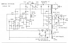
On the diagram I am looking at he has a FET input stage/6SN7 pre and driver stage Driving a RCA-50.
It's a circuit that I have been looking (Just keeps drawing my attention) at for a few years and wondering what all the fuss is about

He also has the modification to drive an 845 to about 4.5Watt per side.
It is the 4 stage topology (Prof. Morikawa)...Apparently the FET has a big effect on the amp (so he says)..The driver stage (cathode follower) is DC coupled to the OP tube..He uses a radio shack automotive choke in the FET supply. I have one from 1970..LOL so it might be a way to use it...
___________________
Regards the OTL I use it most of the time with the Mozener mod works great!
I just want to know what is it thats so special with the 50..Or is it a damp squib..LOL
Regards
M. Gregg
JC has a blog online... you can ask him urself...?
_-_-bear
That sounds interesting..
Do you have the web address?
Perhaps he would post the Schematic in this thread just for interest..
Regards
M. Gregg
I have sent an Email to ask if he would like to comment...
Regards
M. Gregg
hey there, the original "dinosaur" was a fun evolution of the loftin white DC concept, where the bias for the various stages could be somewhat compensated for by the bias of other stages... i don't remember exactly what i did. but i got DC for the FET from the cathode resistor of the output tube. it is related to the "professor morikawa" circuit, but that isn't unique or important. the main thing i learned from that circuit was that a cathode follower solves most of the problems a large output triode creates... especially when the swing necessary to drive them gets above 80 volts peak to peak. cathode followers had gotten a bad name in those days, for various reasons, some real and some fashion. mostly fashion. power triodes are not so easy to drive. they have a variable input impedance that changes with level, and a large grid to plate capacitance. the 50 tube is more so, than many other tubes (more than a WE 300B, but often less than a modern remake). the idea of using an RC coupled driving stage, with a large grid resistor and a high impedance driving stage (all the rage at the time because everyone wanted to make a one or two stage single ended power amp), had bottomed out in my view, because the amps sounded so different at small signal levels than they did, balls out. the highs and bass compressed like crazy and mids got dirty. all amps fall apart when they clip, but this was a "long" oscillatory recovery and slewing... i had begun to really get into testing things. the next obvious step was to drive the output tube with a low impedance driver stage, and to get rid of the cap... the one between the driver and output stage. that led to getting rid of all the caps: an obsessive design feature i have pursued for years.
i should say that others had discovered the same problems, and went the other way: by using interstage transformers to keep the impedance more optimum. i did it too, but the quality of the interstage transformer became an issue. in the mid 80's, all you had was the tango NC16 (i believe that was the number). it was hard to get in the usa. very little of the recycled american interstage iron was good enough. that was when UTC became "you take a chance". there were some peerless parts that were amazing, but it was slim pickings for iron, in those days. it had to have vastly superior bandwidth than the output transformer did, or the two could combine in a destructive way. there were many who didn't care... or, even liked the sound. i accept that. but it wasn't my taste or interest. i was looking to exceed the "high end" hifi sound, not go nostalgic.
the dinosaur was a fun stepping stone to things that came later on. if you look at my blog, there is some discussion of the ideas. "some interesting DC circuits" and other posts. hope this helps?
well, i have used the 211 types more than any other large transmitting types. 845's had already become scarce in the 90's. for me, the tube type is not the interesting thing... it's the end result. they're all good, and on any given day, any one of them might become a favorite. 211's need less swing, but it is not true to say that they are easier to drive. grid current changes are large from quiescent to full swing and make a high performance from a high Z driver (12AX7 or cascode/pentode) not possible. that circuit will work fine with 211s. are there better ways? sure. that is a good simple way to do it, though.
well, i have used the 211 types more than any other large transmitting types. 845's had already become scarce in the 90's. for me, the tube type is not the interesting thing... it's the end result. they're all good, and on any given day, any one of them might become a favorite. 211's need less swing, but it is not true to say that they are easier to drive. grid current changes are large from quiescent to full swing and make a high performance from a high Z driver (12AX7 or cascode/pentode) not possible. that circuit will work fine with 211s. are there better ways? sure. that is a good simple way to do it, though.
Not sure if you noticed my last post..
Is it Ok to post the Dinosaur circuit from sound practices mag or is it copywrite protected?
Its only so everyone knows what is being discussed..
Regards
M. Gregg
well - it must be somewhere here : (new adventures in) ultra‑fi .......
I have a photo...because I have the mag in my hand..LOL
I notice you can run 845 on lower voltage with higher current..
How would you mod for 211?
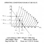
Operation point for 845:
B+ increase to 500v
Bias B- to -50v
10v 3.5A DC filament
dropping resistor for driver change from 500 ohm to 8.2K 3w
Gives 4.7w per channel..
Regards
M. Gregg
How would you mod for 211?
Operation point for 845:
B+ increase to 500v
Bias B- to -50v
10v 3.5A DC filament
dropping resistor for driver change from 500 ohm to 8.2K 3w
Gives 4.7w per channel..
Regards
M. Gregg
Last edited:
- Status
- This old topic is closed. If you want to reopen this topic, contact a moderator using the "Report Post" button.
- Home
- Amplifiers
- Tubes / Valves
- Morrison Dinosaur