Dear All, out of another users's kindness and expertise (lem8r) a design was developed to push a gu81m, full pentode design, into AB2 operation.
the design is attached to this message.
Please feel free to comment....I m just a messenger so hopefully lem8r will jump in to reply to any observations:
Alex
the design is attached to this message.
Please feel free to comment....I m just a messenger so hopefully lem8r will jump in to reply to any observations:
Alex
Attachments
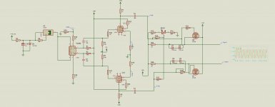
Seems like the long way around... using a KT88 to provide voltage drive to a Mosfet follower?? No power is required, only voltage swing from the tube driving the Mosfet.
I think I'd consider other means myself, and perhaps decide if a Mosfet is what I want or if I want to drive the output tube from another tube or not.
I'm not too sure about the bias means for the Mosfets either, but perhaps that will be sufficient...
_-_-bear
I think I'd consider other means myself, and perhaps decide if a Mosfet is what I want or if I want to drive the output tube from another tube or not.
I'm not too sure about the bias means for the Mosfets either, but perhaps that will be sufficient...
_-_-bear
Well, pentodes are a good idea when you need lots of swing, but yeah, I'm with bear, KT88 is not an optimum choice. I'd scout through some databooks and find a HV pentode with a more reasonable power rating (a few watts, not 35!), then start experimenting. There are some interesting linearization tricks you can do with the pentodes in a differential configuration.
thankyou to both of you for the inputs.
Unfortunately custom transformers must be made to suit specific design requirements. The idea is to have a working design to fabricate transformers....with a working basis experimentation can begin...
I personally do not have enough spare material to simulate this design on a breadboard
What would greatly help would be to have a working design with very good or good chances of working adequately.. Modifications would go from there to an optimized design.
Have you seen this? Apparently it's a working prototype.
http://www.diyaudio.com/forums/tubes-valves/144767-class-a2-direct-mosfet-coupled-se.html
http://www.diyaudio.com/forums/tubes-valves/144767-class-a2-direct-mosfet-coupled-se.html
A custom transformer can be made for this application.
I don't believe it. Biggest I have seen is for the Altec 260. 813 amp, power output under 300W and I will bet against going any bigger w/o significant issues. Go ahead though, I'd love to see how you do it.
cheers,
Douglas
Any idea how much distortion the KT88s produce? I'd bet it is quite a bit.
I got about 1% out of 6SN7s at 200Vrms(540Vpk-pk) with a CCS plate load, and I don't even think that's the best tube to use for this. Not tryin' to brag, just pointing out that fly swatters will kill a fly much better than a hammer any day.
I got about 1% out of 6SN7s at 200Vrms(540Vpk-pk) with a CCS plate load, and I don't even think that's the best tube to use for this. Not tryin' to brag, just pointing out that fly swatters will kill a fly much better than a hammer any day.
Keep in mind, that SRPP was exactly designed to for such an application. Driving low loads with large signal voltages. Unfortunately it only works best with a constant load which isn't case with your AB2 power tube. But since you only need a high supply voltage and two simple tubes (which only see half of the Ub) it could be worth a try.
Personally, if I had to design a driver, I would use a Anode choke and a high gm pentode.
Personally, if I had to design a driver, I would use a Anode choke and a high gm pentode.
A custom transformer can be made for this application. I don't believe it. Biggest I have seen is for the Altec 260. 813 amp, power output under 300W and I will bet against going any bigger w/o significant issues.
Custom, or off the shelf, a GOOD transformer in this power range will not be cheap. If you have a rather large budget you can get an off the shelf 400 watt Plitron toroid here:
400W Special Design Output Transformer
About 5 years ago during a discussion of big powered tube amps a post was made with a link to Plitrons surplus page where a very similar (unpotted) OPT was being sold for a reasonable price. I bought a pair. I measured the frequency response at 100 watts to be 5 Hz to 71 KHz (+/-3db).
http://www.diyaudio.com/forums/tube...807s-push-pull.html?highlight=plitron+surplus
I have used these transformers up to 525 watts in experiments with Petes Red Board. See posts 437 and 438 in this thread:
http://www.diyaudio.com/forums/tubes-valves/151206-posted-new-p-p-power-amp-design.html
Note the power output level and the drivers were common cheap pentodes.
As stated by others, if you are using mosfet followers you don't need a big KT88 for the driver find a pentode that is very linear that has a high plate voltage rating.
I have been doing experiments along these lines for an upcomming screen drive project and find that tubes designed for TV vertical sweep or video output seem the best choice here.
As I have stated before threads about big powered tube amps come and go, but very few 200+ watt tube amps get built because of the high probablilty of failure. A little instability in a 50 watt amp might blow a screen resistor, a tube, or maybe zap a tweeter. A little instability in a 500 watt amp can reduce a very expensive collection of parts to scrap, set your house on fire, or make you dead! Work in small steps and be prepared to tweak, breadboard, and tweak again on each stage. Don't build the whole amp and plug it in!
thanks to tubelab and other who have partecipated....safety precautions are paramount and will be enforced at ALL times...
I am not that keen on killing myself or setting the house of fire (I do have a 3000w isolation transformer and several industrial fuse holders I can use to protect the main lines... LEXAN shielding if necessary will be installed when I will start things up.
as far as the tubes are concerned...
I do have spare 6Jm6 around and can easily find similar deflection tubes for tv use. Plate voltage is fairly high and seem to perform well with local feedback. (redboard docet)
What was your anode voltage on the 6SN7?
400V, 800V supply voltage.
Seems to me that if one can design and afford to build an output transformer of this power to have usable bandwidth, then making or buying an interstage transformer of equal or greater bandwidth would be easy.
Just use an interstage?
Make it work at high power first, then go back and redesign the driver stage, if you still think it is needed?
Also, it can't be that difficult to identify and mail order some tubes that will do the driver job.
Something does not add up quite right on this project.
_-_-bear
Just use an interstage?
Make it work at high power first, then go back and redesign the driver stage, if you still think it is needed?
Also, it can't be that difficult to identify and mail order some tubes that will do the driver job.
Something does not add up quite right on this project.
_-_-bear
hey-Hey!!!,
I agree Bear, it does nto add up...")
From a B+ of 1kV( outside edge of manageable ) and a 400 mA/tube idle point. Run g2 at 600 V. A load of between 4 and 5k a-a is called for for Class A. You'll get ~ 1k8V across the primary WITHOUT crossing into positive grid current territory( about 170V p-p g1 signal). Now this one will have a leaky grid...
Consider a few volts on g3 to square up the low plate voltage side of the curves.
cheers,
Douglas
I agree Bear, it does nto add up...
From a B+ of 1kV( outside edge of manageable ) and a 400 mA/tube idle point. Run g2 at 600 V. A load of between 4 and 5k a-a is called for for Class A. You'll get ~ 1k8V across the primary WITHOUT crossing into positive grid current territory( about 170V p-p g1 signal). Now this one will have a leaky grid...
Consider a few volts on g3 to square up the low plate voltage side of the curves.
cheers,
Douglas
Seems to me that if one can design and afford to build an output transformer of this power to have usable bandwidth, then making or buying an interstage transformer of equal or greater bandwidth would be easy.
Just use an interstage?
Make it work at high power first, then go back and redesign the driver stage, if you still think it is needed?
Also, it can't be that difficult to identify and mail order some tubes that will do the driver job.
Something does not add up quite right on this project.
_-_-bear
Not meaning to sound harsh,butwhat is it that does not add up about the project?
I can order any tube is required for this operation. The point being I have limited spare material (output transformers, HV cable, power transformers which can supply that voltage with THAT much current) therefore I have to have a working "backbone" which will be there if, during future experiments, I see there is need for an interstage transformer.
Consider that I will need three chassis
3x 120 eur
transformers: at least 600 euros worth
cable (teflon/silk good for at least 20kv) and sockets 100 eur (by the way....the GU81m sockets cost 25 euros each and are 100 euros more to the list)
So you see well over 1500 eur before I start soldering and I guess very few people on the forum have the kind of spare material to set a project like this in motion without buying anything
If the project has a fair chance of succeeding I'd rather get a backbone working, secure HV connections and PSU, adequately feed 12.6@44A to the output tubes with little or no noise,buy and implement chokes and capacitors for 1600@several mA, test those out and then, finally get back to the driver section and tweak everything into an optimal design. Also I said nothing about timing retard and main AC softstart or safety concerns with careful chassis layout.
I'd rather not have this project on a breadboard since I am NOT that confident in my ability to secure my workspace against the kind of voltages envolved.I'd rather transfer everything into a chassis.
Also bear in mind there are further safety concern. Bleed resistors across capacitors are not a joke on this project. 1600v over 4700uf worth of capacitors in series demand for some serious calculations.
Once I have
1. main b+ for output and drivers
2.secondary HV voltage for outputs (g2)
3. bias voltage for output
ecc
i can mess around with GU81m designs. This is not a project I think anyone can tackle by sticking things together. It's another "class" of amplifiers which demand specific technical solutions.
My concern is to have some good feedback on aviable design. If we all agree one design can get things "rolling" I will build the amps. Once built and tested I will be sure to ask you all again for ways to increase performance (having done all necessary probing with my oscilloscope and meters).
- Status
- This old topic is closed. If you want to reopen this topic, contact a moderator using the "Report Post" button.
- Home
- Amplifiers
- Tubes / Valves
- High voltage driver for AB2 operation GU81m tubes