Thanks! I really appreciate the encouragement!
Actually work is progressing much more slowly than I would like. What really helps is to think things over and over...really imagine the assembly in every aspect before even touching the screwdriver. This way when the time comes to build, every forseen problem is addressed swiftly (obviously there is a margin for error). I think the amp will work well. In any case the driver section can be redesigned and swapped for something better in a very short amount of time. I am eager to test the power section. Once that is done it will just a matter of starting the testing phase.
I think the bass response will be really exceptional. Many have described music played by large tubes as "effortless". can't wait to corroborate this idea!
here is the video
http://youtu.be/F8Jh4s9j9rk
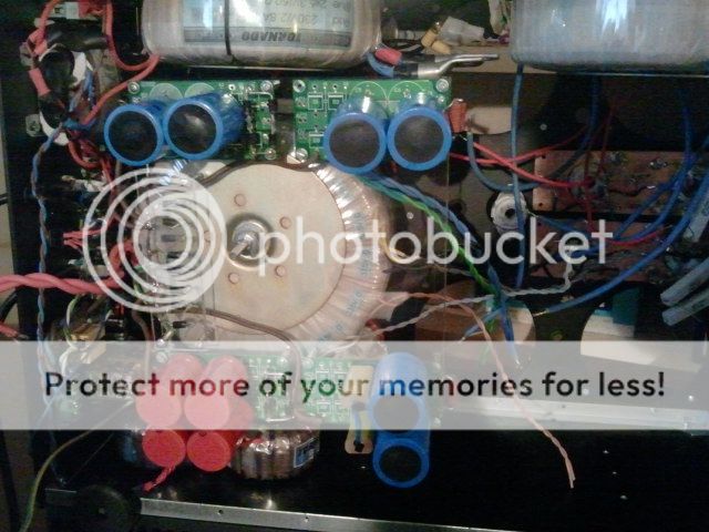
the filaments are sofstarted via a 4A 10ohm NTC thermistor....the main switch triggers the timer which in turn activates the softsart module. This will force the surge to flow through 4x NTC thermistors. After 1.2s the thermistors are bypassed by a relay.
http://youtu.be/F8Jh4s9j9rk
the filaments are sofstarted via a 4A 10ohm NTC thermistor....the main switch triggers the timer which in turn activates the softsart module. This will force the surge to flow through 4x NTC thermistors. After 1.2s the thermistors are bypassed by a relay.
Last edited:
go slow...haste makes waste...are you affected by the earthquake?
Very true. The best part is yet to come...for now it is just boring mechanical work. I still have to wait for the sockets to be sandblasted and powdercoated.
Thanks for the question. Very kind of you. Luckily no I live in the least sismic area of Italy and just felt the smallest amount of tremors. At 9 o'clock yesterday the tremor was noticeable but not cause for concern.
The amp is so heavy I was pretty confident nothing could happen.
burning tubes...
all filament transformers in the amplifier are connected to mains via a NTC thermistor (CL-60) 10ohm @ 25°C
Only the rectifier filaments do not draw enough power to lower the thermistor's resistance to an acceptable value...therefore with only the rectifiers on I get 2.1v instead of 2.5v.
I hope this will solve itself when the gu81m filament transformer will draw its own current.
for now...some burn in tests
xenon

mercury

If anyone has any suggestions for ux4 compatibile rectifiers I am all ears (no pun intended). This will be a great testing platform for future experiments
all filament transformers in the amplifier are connected to mains via a NTC thermistor (CL-60) 10ohm @ 25°C
Only the rectifier filaments do not draw enough power to lower the thermistor's resistance to an acceptable value...therefore with only the rectifiers on I get 2.1v instead of 2.5v.
I hope this will solve itself when the gu81m filament transformer will draw its own current.
for now...some burn in tests
xenon
mercury
If anyone has any suggestions for ux4 compatibile rectifiers I am all ears (no pun intended). This will be a great testing platform for future experiments
Also a question...
I want to move inputs and outputs to the front of the amplifier

the front plate is 10mm thick. I can get away with it as far as the outputs (since the threaded connectors are very very long) but input s going to be a problem. Can anyone point out a connector, with a round footprint, which will mount on a 10mm thick panel? I thought of 6,3mm jack or RCA but both seem too short.
I want to move inputs and outputs to the front of the amplifier
the front plate is 10mm thick. I can get away with it as far as the outputs (since the threaded connectors are very very long) but input s going to be a problem. Can anyone point out a connector, with a round footprint, which will mount on a 10mm thick panel? I thought of 6,3mm jack or RCA but both seem too short.
Also a question...
I want to move inputs and outputs to the front of the amplifier
the front plate is 10mm thick. I can get away with it as far as the outputs (since the threaded connectors are very very long) but input s going to be a problem. Can anyone point out a connector, with a round footprint, which will mount on a 10mm thick panel? I thought of 6,3mm jack or RCA but both seem too short.
Is the front panel removable?
If so what you need is a counterbore. A counterbore is a drill - for example that begins as say a 6mm drill further along it becomes like an end-milling cutter, so you might have say a 6mm pilot hole followed by a 22mm flat cut. With care this would enable you to reduce the thickness of your panel where needed,
Paul
machining parts in Milan is very expensive. Many ask an insane amount of money just to place their hands on a piece of metal !
I found this which is quite nice
Neutrik NJ3FP6C-BAG 1/4 Jack Chassis/Panel Socket Black | eBay
I have a 24/25 drill for aluminum which will cut a hole for it in the panel. Neutrik is a good brand.
I found this which is quite nice
Neutrik NJ3FP6C-BAG 1/4 Jack Chassis/Panel Socket Black | eBay
I have a 24/25 drill for aluminum which will cut a hole for it in the panel. Neutrik is a good brand.
@djn thanks! I spent a lot for this project already.... had to buy a set of 40 metal HSS drillbits...plus several large hole type drills (22mm to 120mm). I'd rather just drill a 24mm hole and be done with it. ") Also I have a very flimsy vertical drill.....
Also I have a very flimsy vertical drill.....
The HV transformer has already posed a lot of problems...spikes, vibrations...all related to the size we reckon. I got my pots for volume and can start drilling the front panel.
it'll be some time before I can get down and solve the various bugs.
For one I had to buy surplus 150w resistors (4 of them) to create a load for the 1,3kv line. Otherwise the transformer's temperature exceeds the factory limit.
Stay tuned. I will get thin running eventually and thank you for the kind words and advice
Also I have a very flimsy vertical drill.....The HV transformer has already posed a lot of problems...spikes, vibrations...all related to the size we reckon. I got my pots for volume and can start drilling the front panel.
it'll be some time before I can get down and solve the various bugs.
For one I had to buy surplus 150w resistors (4 of them) to create a load for the 1,3kv line. Otherwise the transformer's temperature exceeds the factory limit.
Stay tuned. I will get thin running eventually
and thank you for the kind words and advicemachining parts in Milan is very expensive. [...
Yes, and parking is a pain too!
Paul
okey dokey...(is this the correct spelling? )
something weird I really need somebody's help on.
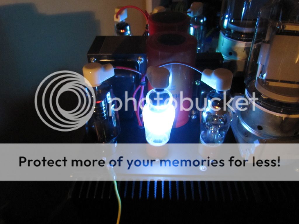
In the photograph you see the 866A glowing. that is the screen (600v) section of the PSU
right...I did all the circuitry one more time and it still glows. I need help to understand why
The circuit is as follows:
hybrid bridge (diodes + tubes) ---- hammond 10H 53ohm choke ---- 2x 4700uf 350v caps in series with 100k balancing resistor each.
Could the glow be the capacitors charging? These are abnormally high values for tube applications so it might stand to reason that the charging process is demanding a lot of current from the tubes.
Please if anyone can help please do so
)something weird I really need somebody's help on.
In the photograph you see the 866A glowing. that is the screen (600v) section of the PSU
right...I did all the circuitry one more time and it still glows. I need help to understand why
The circuit is as follows:
hybrid bridge (diodes + tubes) ---- hammond 10H 53ohm choke ---- 2x 4700uf 350v caps in series with 100k balancing resistor each.
Could the glow be the capacitors charging? These are abnormally high values for tube applications so it might stand to reason that the charging process is demanding a lot of current from the tubes.
Please if anyone can help please do so
okey dokey...(is this the correct spelling?
something weird I really need somebody's help on.
In the photograph you see the 866A glowing. that is the screen (600v) section of the PSU
right...I did all the circuitry one more time and it still glows. I need help to understand why
The circuit is as follows:
hybrid bridge (diodes + tubes) ---- hammond 10H 53ohm choke ---- 2x 4700uf 350v caps in series with 100k balancing resistor each.
Could the glow be the capacitors charging? These are abnormally high values for tube applications so it might stand to reason that the charging process is demanding a lot of current from the tubes.
Please if anyone can help please do so
2350uF is enormous (why so?) and although of course you are choke input it might be worth looking at this
Paul
I read that page, thanks Paul.
I respected the choke input requirements and believed that could be enough. Apparently there is an upper limit to the cap rating after the choke. Could this explain the 0v?
all other voltage read perfectly spot on.
PS my attempt was to provide perfect regulation for screen voltage without going through a regulator. Did I over do it?
I read that page, thanks Paul.
I respected the choke input requirements and believed that could be enough. Apparently there is an upper limit to the cap rating after the choke. Could this explain the 0v?
all other voltage read perfectly spot on.
Yes well I have no experience with mercury rectifiers, but part of the problem might be due to the colossal capacitance you have there; why did you feel that you needed all that? Try substituting something like 8uF which is what the 866s probably were expecting to see!
P.
guess you are right....I used duncan's PSUDII to simulate the circuit and it works...guess I found a bug
Can excessive capacitance drop the voltage to 0?
What is the science behind that? (Thanks Paul for helping. I am just very curious as the results in real life dierge greatly from duncan's software)
Can excessive capacitance drop the voltage to 0?
What is the science behind that? (Thanks Paul for helping. I am just very curious as the results in real life dierge greatly from duncan's software)
- Status
- This old topic is closed. If you want to reopen this topic, contact a moderator using the "Report Post" button.
- Home
- Amplifiers
- Tubes / Valves
- High voltage driver for AB2 operation GU81m tubes