That is where i intended to place them. 4 12v fans with a series parallel switch for silent or power use. I guess i was unclear. The sockets thmselves will be 20mm elevated from the chassis with brass spacers. Thanks for the observations!
Inviato dal mio GT-I9001 con Tapatalk 2
Inviato dal mio GT-I9001 con Tapatalk 2
Compared to premature failure of various components due to a cramped layout I would think reworking the chassis would actually be a pretty cheap fix in comparison to replacing one of those valves.
I agree. Regardless of fans I believe that if those big valves are operated at a proper operating point then they will overheat simply due to radiated heat.
It was only the other day that I was shocked by how hot a finned aluminium heatsink (about four inches square) became just absorbing the heat from four TO220 devices dissipating a few watts each! Here we are talking of four valves whose filaments require about 480W in total and with anodes dissipating what? At just 1kV and 300mA each we're looking ata substantial electric fire aren't we?
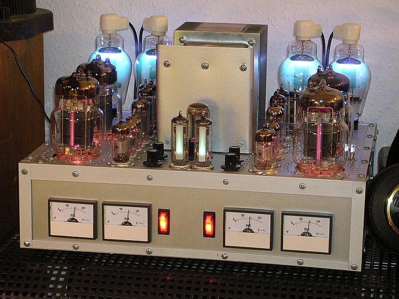
Ma che belle queste stufetteAn externally hosted image should be here but it was not working when we last tested it.
")
Do you own the book 'Building Valve Amplifiers'? It talks about the exact things you are asking about. As others are stating, you have a massive amount of radiated heat to deal with. Fans are not going to stop the large amount of radiated energy from one anode being absorbed by the anode next to it. As well as spacing, you need to consider orientation. The 'flat' face of the anode is going to radiate (and absorb) more heat than the narrow face. You should therefore have the anodes facing away from each other, such that one anode's radiated heat is not absorbed by its neighbour.
And another thing...
24 euros is cheap indeed for such splendid valves, but a melt-down could well cost more than a valve or two...
I have 8 gu81m and can source more @ 24euros each.
I think some forced air cooling will have to be installed. Maybe some thin 20mm fan... Will have to look into it.
Inviato dal mio GT-I9001 con Tapatalk 2
24 euros is cheap indeed for such splendid valves, but a melt-down could well cost more than a valve or two...
Many things are actually theoretical. Rf interference refers to external rf equipment. I have listened to bare circuits while burning in a huge mercry rectifier and no interference was audible in the audio band. I suppose a radio would have been blanked. Did not try
Inviato dal mio GT-I9001 con Tapatalk 2
Inviato dal mio GT-I9001 con Tapatalk 2

Thank you to all for the contributions. I appreciate every single input.
what I have done:
1. the gu81m in he "middle" between the rectifiers and the fron output tubes have been turned so that the anode plate is sideways. I can't do the same thing for all four tubes as the gu81m need to be slided in their sockets. It requires some clearance and if I turn the tubes with the plates facing sideways I can't get the tubes in their sockets.
2. I have marked the holes for installing a thin 200mm fan (actually 2 of these) between the output tubes and the driver tubes. Just connecting spots so I can experiment with different fan sizes.
What I will do:
1. keep a thermal sensor in my head at all times. I fear an IR thermometer will not cut it so I will rely on contact measurements. The operating point for all four tubes will place me in the 1400w range (total filament + anode dissipation).
2. Try to look into shielding. Lem8r suggested this as IR can be effectively blocked thus keeping radiated heat down.
3. verify once and for all the issue of RF interference. I have six slots. MV and XENON rectifiers. Plenty of ways to test for scatter.
This amplifier has the potential to surpass the Philips 1000w unit in every way. Please bear with me. The first lights are a matter of days away.
By all means:.
It is a EL6471
1000W Amplifier Philips EL6471 at full power - YouTube
Powerful yet ugly piece of equipment
I only hope to make an amplifier much more pleasing to the eye
It is a EL6471
1000W Amplifier Philips EL6471 at full power - YouTube
Powerful yet ugly piece of equipment
I only hope to make an amplifier much more pleasing to the eye
the philips amplifier is dangerous:
1. exposed wiring
2. exposed anode connections
3. high gravity center of the truss structure.
In my amp:
Every external cable is 20kv good, every anode connction is either ceramic or teflon cap. The amp will have a very low gravity center with high friction rubber feet.
In essence you could stick your hand anywhere in my amp and nothing would happen except getting heat burned.
By all means:.
It is a EL6471
1000W Amplifier Philips EL6471 at full power - YouTube
Powerful yet ugly piece of equipment
I only hope to make an amplifier much more pleasing to the eye
I think it's beautiful, we are fortunate to be able to see it in operation. I love functionality.
Normally it would have been installed in a chamber with interlocked doors etc. to obviate risk of shock etc. as was the practice with radio transmitters, radar etc.
Meanwhile here's another video of the amplifier - wonderful stuff!
An externally hosted image should be here but it was not working when we last tested it.
An externally hosted image should be here but it was not working when we last tested it.
even if completely covered replacing the tubes would expose the operator to contact with (possibly) non fully bled circuits.
- Status
- This old topic is closed. If you want to reopen this topic, contact a moderator using the "Report Post" button.
- Home
- Amplifiers
- Tubes / Valves
- High voltage driver for AB2 operation GU81m tubes